Introduction to Rhino
v0.2 by Ger Walsh - October 2025
Setup and General Navigation
When you first open Rhino, you are shown 4 viewports. Click the name of a viewport, eg. Perspective to maximise one of them.
Type in commands like ZE, followed by Enter or Spacebar (Zoom Extents) or ZS (Zoom Selected). Use the mouse-wheel to zoom. Hold right-click and draw to rotate. Hold Shift while right-clicking to pan. (Without a mouse, navigation is possible with a trackpad, but specifics may depend on your laptop settings).
In general, in Rhino, typing commands automatically goes to the command bar. Auto-prompt completes and suggests the commands as you type. It also gives you some feedback here and tell you if it needs more information (eg., ExtrudeCrv's response includes and option BothSides, B is underlined and you can type 'b' and hit space or enter to toggle this option. With commands that need a distance, eg Copy/Move, click your base point, type a number, hit Tab on your keyboard to lock the number and then use the mouse to snap to the right angle/direction. If you follow what it says in the command bar, you can do this out of order, or do other options).
Use your mouse to make a selection. Dragging Right-to-Left, or Left-to-Right selects with a crossing, and non-crossing selection box respectively. Hold Shift while clicking to add something new to your selection, Ctrl to subtract. Click away to deselect all.
Rhino has commands like AutoCAD, try:
Join,CloseCrv,Line,Polyline,PlanarSrf,PointsOn/POnandPointsOff/POff,SetPt,CurveBoolean.
At the bottom of your screen, you have some toggles. It is useful to turn on Gumball, turn off Ortho, and turn on OSnap. (May look a bit different on Windows).


The Gumball is/are the arrows and handles that come up when you have something selected. The arrows move (Press Alt once while moving to make a copy). The handles are to rotate (clicking allows you to type in a value). The square tags allow you to do some basic scaling about the object centre (experiment with Ctrl, Alt and Shift in combination with this).
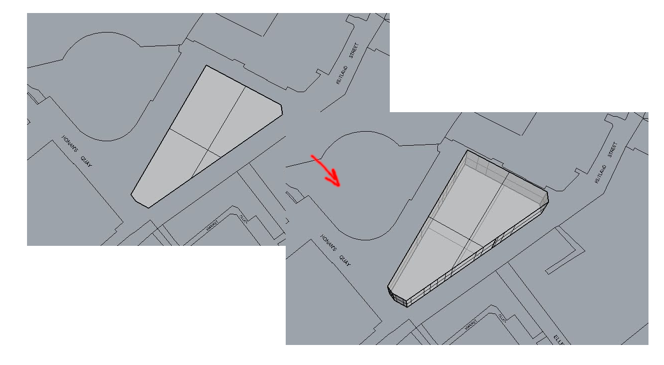
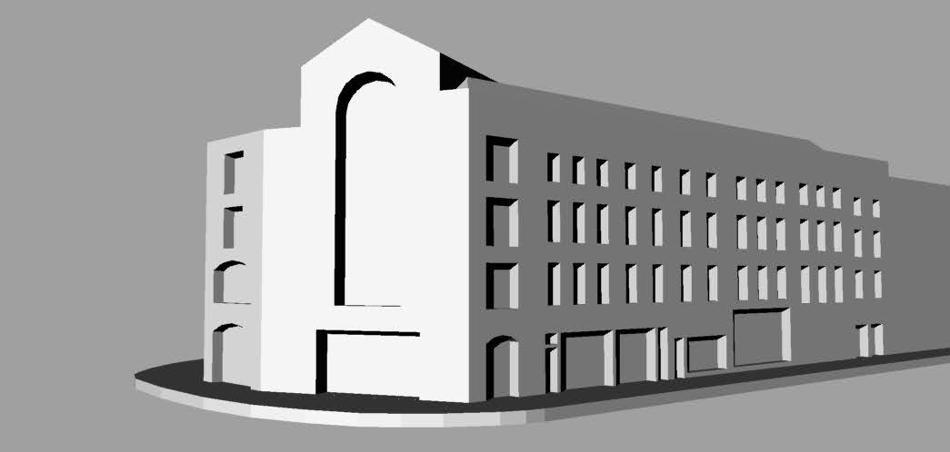
A workflow with some basic volumes
Start getting a clean building outline as a Polyline. Making a PlanarSrf, as below, out of it is optional. Then use the command ExtrudeCrv or ExtrudeSrf.
Getting Photo Elevations
Equipment like a tilt-shift lens is traditionally used for survey photography as it minimises distortion effects due to perspective allowing surveyors to take elevation photographs that can become the basis for making estimations when it may not otherwise be possible to measure. While we did some research and initially intended to purchase one of these lenses. The Tilt-Shift Lens mentioned above makes it possible to rectify more or your image with the building facade by moving the Image Plane. Instead, we used software to rectify and stitch images for us, adjusted for lens distortion, and cropped to the elevation outline. See below.
The Photo Elevations are used mostly for reference. Therefore this is possible with a less expensive camera.
- A. Photo-rectification with Photoshop
(Click here to expand).
(Click here to expand).
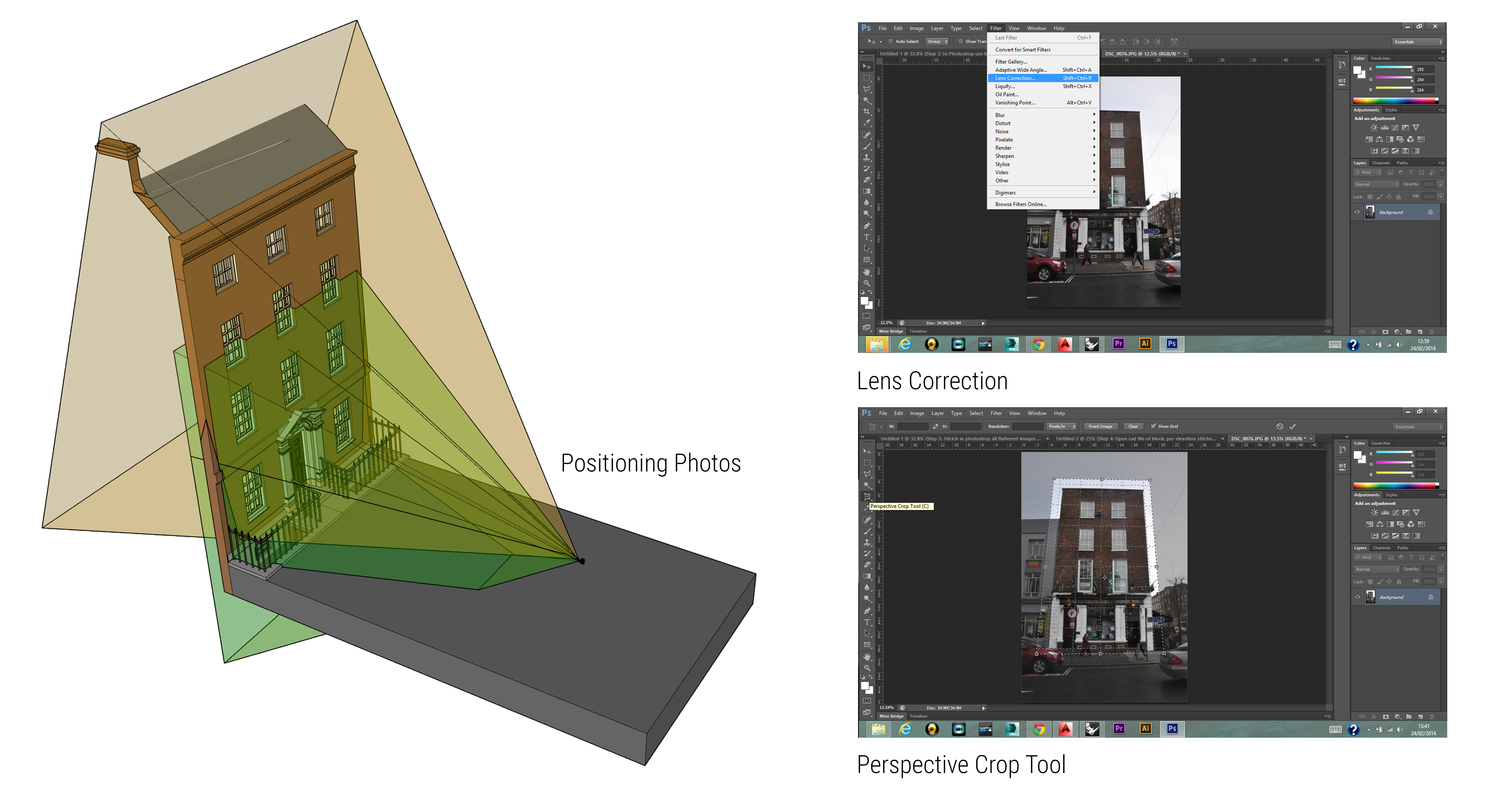
First use the `Perspective Crop Tool`. Place a distorted rectangle. When you hit ok, it will do the transform and the crop in one step. You lose the proportions of the photo, but you can get it pretty close by eye now and fix it in the next step.
You *can* reference a CAD file, and with the vertical heights (link to Rhino step) to determine the proportions of your canvas. However, you don't need to be so exact. We can use the `Scale1D` function to correct the aspect ratio.
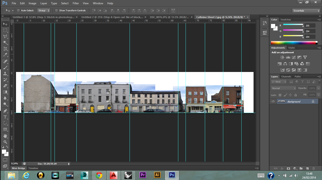
If you have already cropped individual facades on the same street, you can use one of the Photomerge options to stitch them **(File > Automate > Photomerge)**. Be sure to enable **"Reposition"** mode to ensure that the images are scaled and rotated to best fit.
Photoshop generally applies layer masks. If you don't need to reposition anything, you can `Merge All` layers (right-click on the layer list), and if it's a very large file, use `Image > Image Size` to set the number of pixels. If it hasn't compressed it too much - that you can reference the position and rough dimension of doors, it will be a lot easier to work with later.
- B. Photo-rectification with GIMP
(Click here to expand).
(Click here to expand).
In GIMP, use the Perspective transform tool (`Shift+P`). Enable **"Corrective"**, and clipping to **"Crop to result"**. (Try other Clipping and Guides options for yourself).
To use, click the tool, drag the corners of the current layer until they're over an oblique rectangular plane, and press Enter or the `Transform` button on the popup.
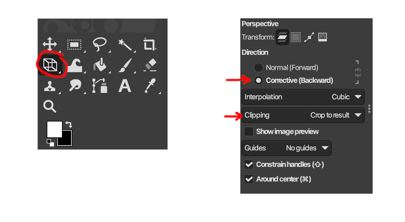
Use normal transform tools to arrange multiple layers together. And the Handle Transform (`Shift+L`), which is a more advanced tool to tweak skew and perspectives together. There isn't an automatic photomerge/panorama tool in the core GIMP program.
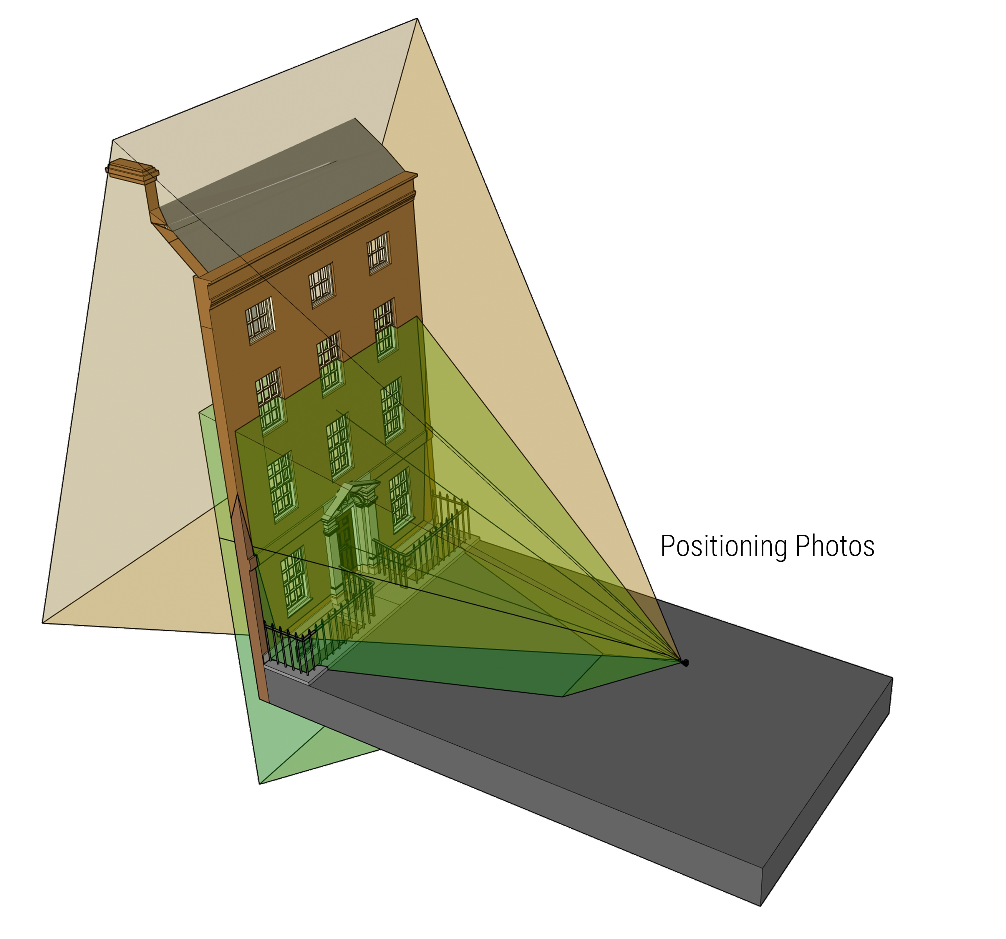
- Importing. Use the
Picturecommand, and choose the location of your file to import. Your first click sets the bottom left corner (having o-snaps set here helps a lot!), second sets the bottom right.
Use Rotate3D to rotate about the line at the base of your building volume; click the start plane, click to reference the angle of the facade to finish.
Use Scale1D to adjust the 'height' of the photo.
Using the Topography Files to reference heights
Measure a vertical line from a point on "L2-Landscape" to a point on "B-Roofscape" to give you the height of a building at that point. Or inspect the properties of a point on the roofscape layer to find its "Z" value, which is its height above the 0m reference.
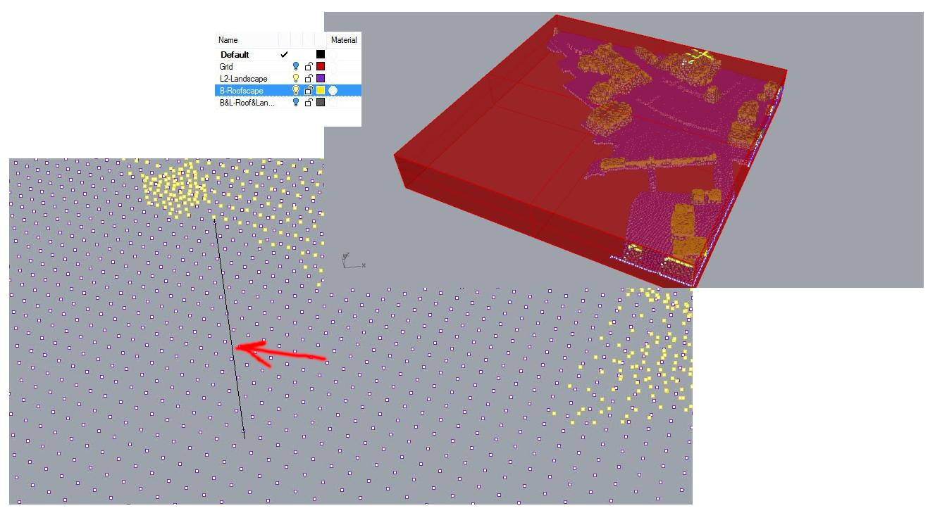
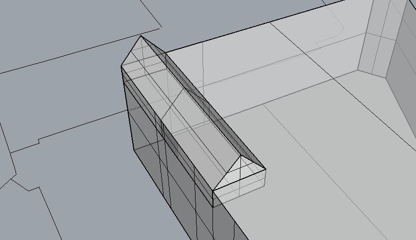
Add volumes for the roof, referencing these heights. Just ensure that they are combined as cleanly as possible at te end. Use BooleanUnion, MergeAllCoplanarFaces, and ShrinkTrimmedSurfaces.
The command Picture, allows you to insert a JPG, PNG etc. as you've previously prepared. You can click corners in your solid to align the picture. You can use Scale1D perpendicular to the elevation after, if the proportions aren't right.
Example with roof complete and elevation images imported:
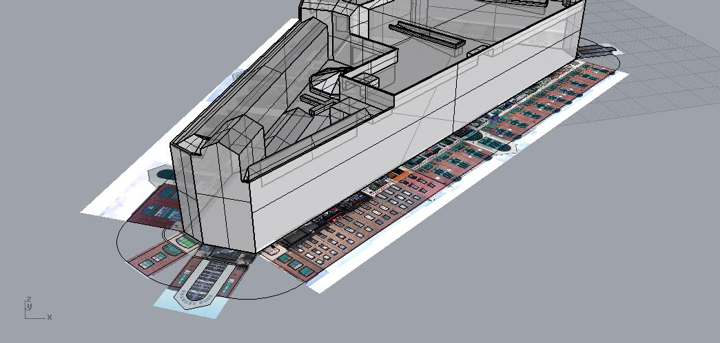
Nice!
Adding Window and Door Features
Commands:
Rotate3D,Move(reference OnTan/Perpendicular from the object edge),ExtrudeCrv, and either toggle the optionClosed, or use the commandCapafter,- Window extrusions were typically done to 500mm into the building. (as you hover, over a point, or where it says Near, the bar at the bottom will show numbers for X, Y, Z coordinates and then current distance, so you know)
BooleanDifference: select the building, Enter or Space, select multiple shapes to subtract.
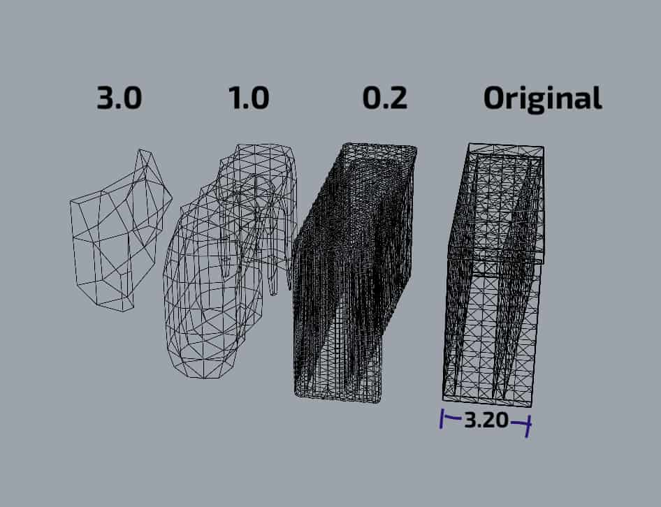
ShrinkWrap
Link: https://docs.mcneel.com/rhino/8/help/en-us/commands/shrinkwrap.htm
New command in Rhino 8, _ShrinkWrap creates a mesh around selected geometries. It will join and smoothe selected geometries and can sometimes be a way to repair broken or hard-to-repair geometry for, for eg, 3D Printing. Because there isn't an upper limit to the amount of smoothing and re-meshing. High numbers can affect your computer performance and model size.