3D Routing*
v0.1 by Ger Walsh - July 2023
* True 3D Routing requires something like a five-axis machine or a robot arm. The following are techniques that achieve something similar, but have certain limitations in each case.
2.5D Routing
2.5D routing is the name commonly given to a technique to produce 3D pieces on a 3-axis router, like our ShopBot. The tools that you use are mounted vertically. They can move in X, Y, and Z. However they cannot rotate in, what is called, the "A" or "B" axes. Vertical contours can be achieved by moving the vertical and horizontal axes at the same time.
V-Carve Pro (as well as Aspire, AlphaCAM and others) can accept 3D files (typically in .STL format, also Rhino 3DM, and SketchUp SKP files).
On import, set your axis, rotation and dimensions. Set a 'cutting plane' - Below this everything is disregarded, it allows you to focus on the top surface of a model. If you would like, it can use this plane to split the model, rotate the underside and present that for 3D routing, so that you can assemble both parts after.
Note: You also have the possibility of rotating the model and preparing 3D profiles of the other side. In this case alignment is very important. Have a look at this tutorial from Shopbot to see what is involved.
For 2.5D routing, you need to learn 2 new toolpath types,
- The Roughing Path, and
- The Finishing Path.
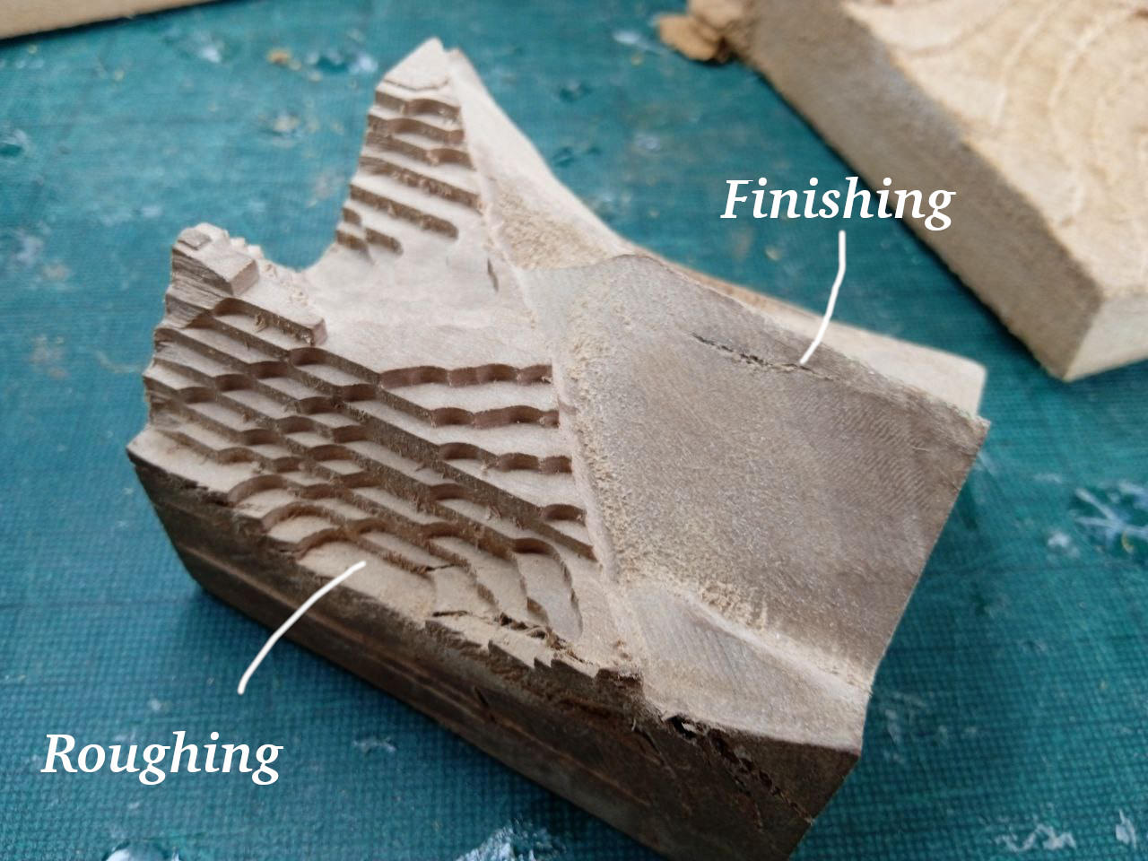
The Roughing Path is made of generated horizontal paths, cut in a raster pattern, to rough-ly give you the 3D volume. The contours can look stepped and rough. The main purpose is to remove most of the material, to allow using a finer finishing tool. For most purposes, an 8mm Round-nosed bit or a 6.35mm Downcut bit will work well here.
A Finishing Path, by default has vertical contours and a large pass-over ratio applied, ie. how much a given line overlaps with the previous and next. Typically we would use a tapered-4mm ball-nose bit here.
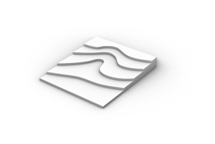
Contours (technically only using 2D toolpaths)
Using successive 2D pockets, you can create a cascading 3D surface. If you are representing a landscape, this could be a good choice. You can start from a .DXF file (or similar) and you can prepare everything with a 2D CAD program.
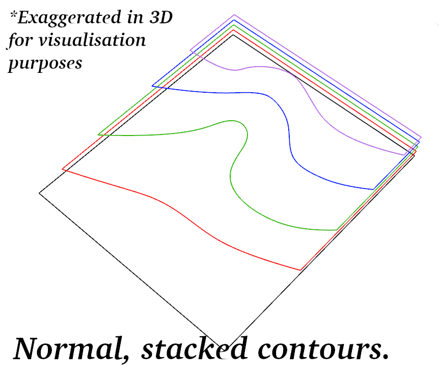
You should make sure:
- Each contour is a joined, closed polyline. The CAM program only cares what is cut away, so you may have to continue the polyline around the border, but you need to make sure it is on the negative side.
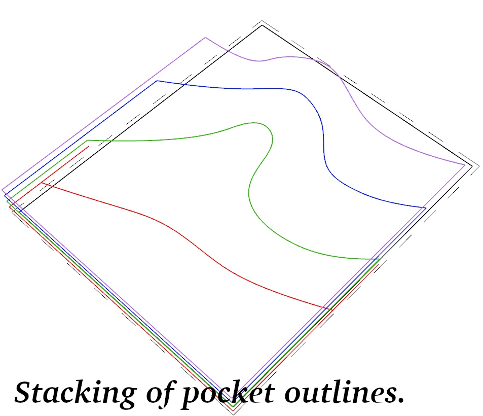
- Your contours should be cascading, meaning that each contour is within the previous(above) contour.
- Be aware of your max cutting depths. And if using a large-area clearance tool(see note below), it can typically only plunge 1mm at a time. The tool profiles in V-Carve Pro are set up to divide it in multiple passes where necessary.
Note that while there is a lot of flexibility in this method, you most likely don't want to use your finer tool for the large-area clearance that might be required. In setting up a Pocket toolpath, you can set a second clearance tool, for instance the 2.5"(63mm) spoilboard cutter. You can cut all of the work associated with that tool first, so it doesn't add inadvertant tool changes. And it still saves a significant amount of time!
Stacking, or Interconnected Slices
This is a technique to slice a 3D object in software and export 2D cuts, which you can then lay out and cut on a laser cutter or a CNC router.
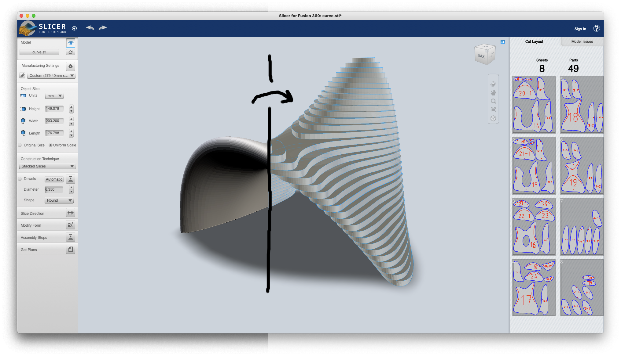
The most popular program to do this is AutoDesk's Slicer for Fusion 360. At the time of writing the standalone version is still available for download, but AutoDesk have indicated that they will not support this in the future and may remove this link at any point.
This can also be done with an Add-on for Blender, and many examples of people doing it in Grasshopper (though there isn't a definitive script we have come across). Example_1 by Fernando Rosa Belmonte. It would be definitely possible for someone to script in Python or something else.
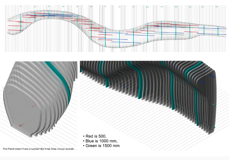
One example, which is further documented here. This project didn't use any of the above shortcuts. Due to project requirements, it had to be done manually. So intersecions were carried out, and cutting sheets were layed out in Rhino.
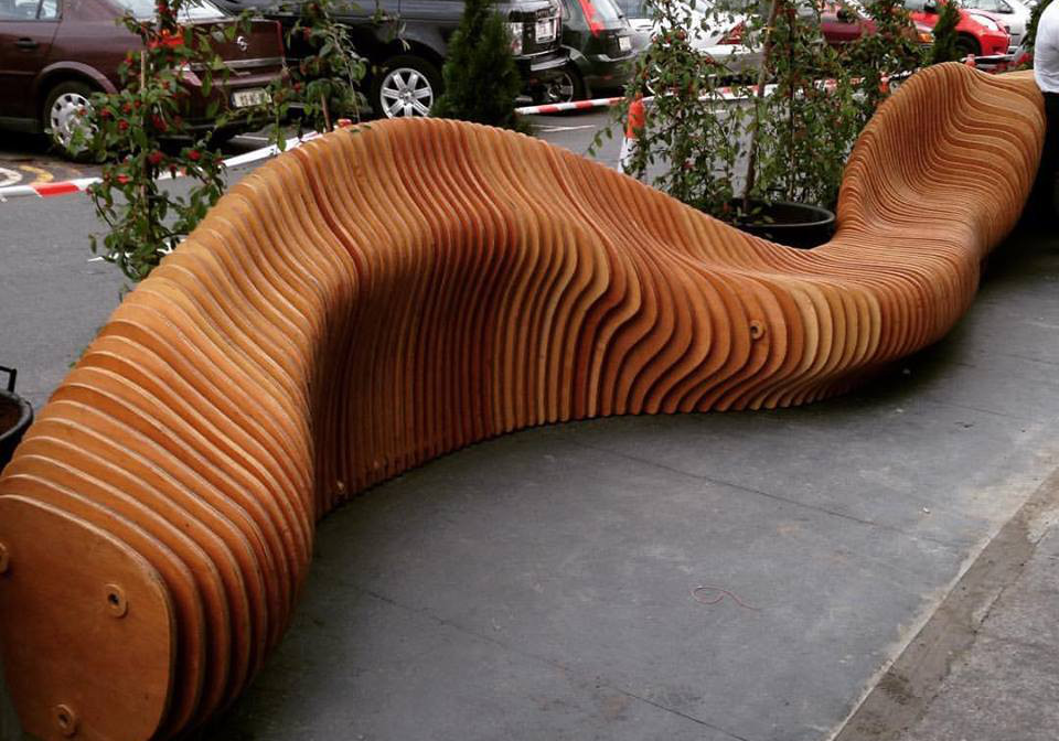
Some have used this technique, sanded to remove the stacked look or as a frame, for material like Papier Mâché or Rice Paper to make a 3D sculpture.
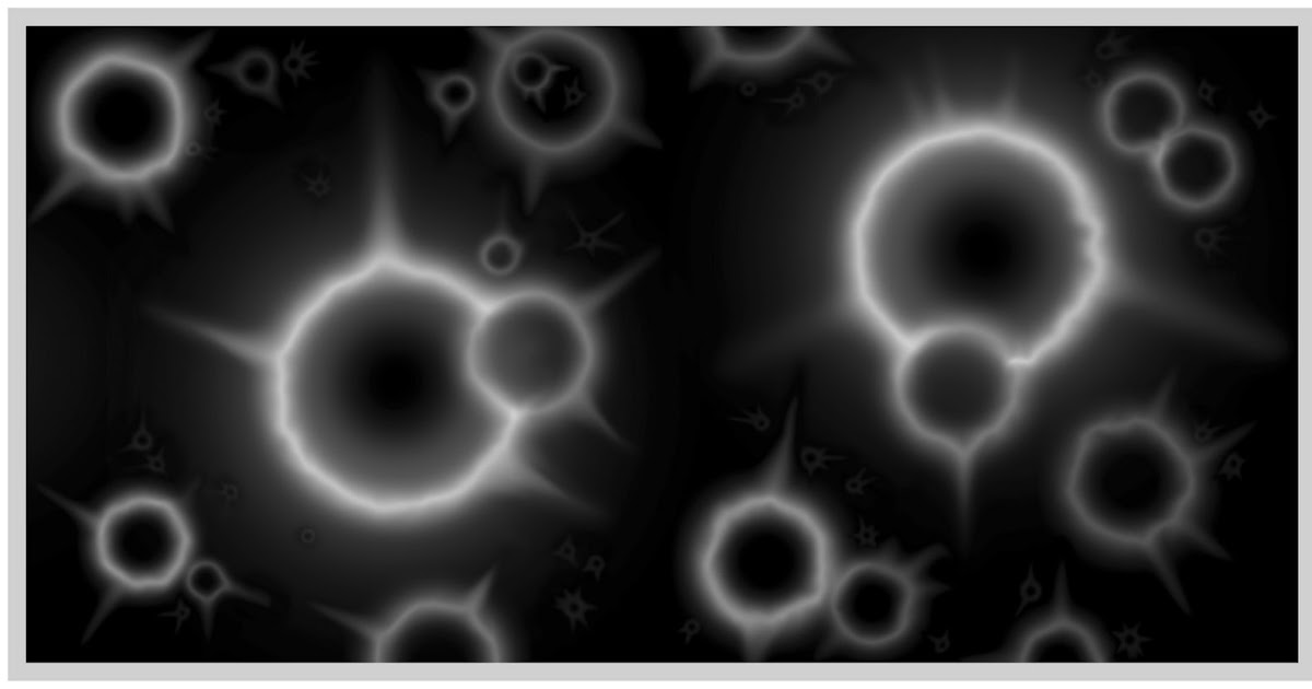
Using Greyscale Depthmaps
A greyscale depthmap is an array of pixels from black to white. The height, in 3D, is represented by the greyscale value (which can be from 0 to 255). This is an effective way to store relief data, but does not allow anything more complicated.
The technique of using a greyscale depthmap is discussed on this forum page, and in particular this response by user JeremySimmons, who does the following experiment.

To do this yourself, you can
- search online for terms like "3D greyscale Depthmap" etc.
- Use one of the free online Lithophane generators to get an .STL file. This is meant for 3D printing lithophanes, but we are able to use for our purposes too.
- Create a new file in V-Carve Pro, entering your material dimensions, etc. Import your .STL using the modelling panel on the left. And follow the usual steps from there.