ShopBot, Step-By-Step
v0.3 by Jen O'Riordan and Gerard Walsh, March 2025
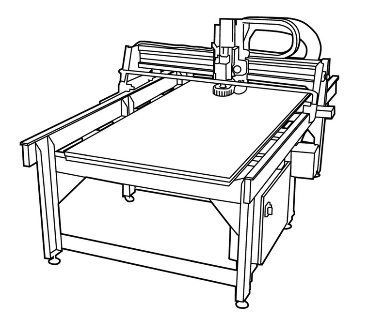
This is a guide to the ShopBot PRSAlpha 96"x48" CNC Router.
Pre-flight check
To use the CNC router, you must have completed an induction with Fab Lab staff, you must obey the Health and Safety requirements of the Fab Lab Workshop, and wear all appropriate Personal Protective Equipment, and follow any other guidance outlined in our Health and Safety Documentation.
Before beginning, ensure the bed is clear, that there are no obvious faults, for example loose cables, unfixed panels, and ensure the machine is generally unobstructed. If you have any doubts, do not operate the CNC, and contact one of the Fab Lab staff.
Steps:
- Starting/Setting Up the machine,
- Loading bits and material,
- Sending a job to the machine,
- Running the job.
Starting/Setting Up the machine
Assuming you are happy with the safety steps above, turn the isolator to On, if it's not already.
Start the computer, and run the ShopBot3 Controller program. SB3 is used to control the machine, setting up, and sending jobs. Its icon is in the toolbar, at the bottom of the screen:
![]()
- SB3 is used to set up the machine.
(Click here to expand).
(Click here to expand).
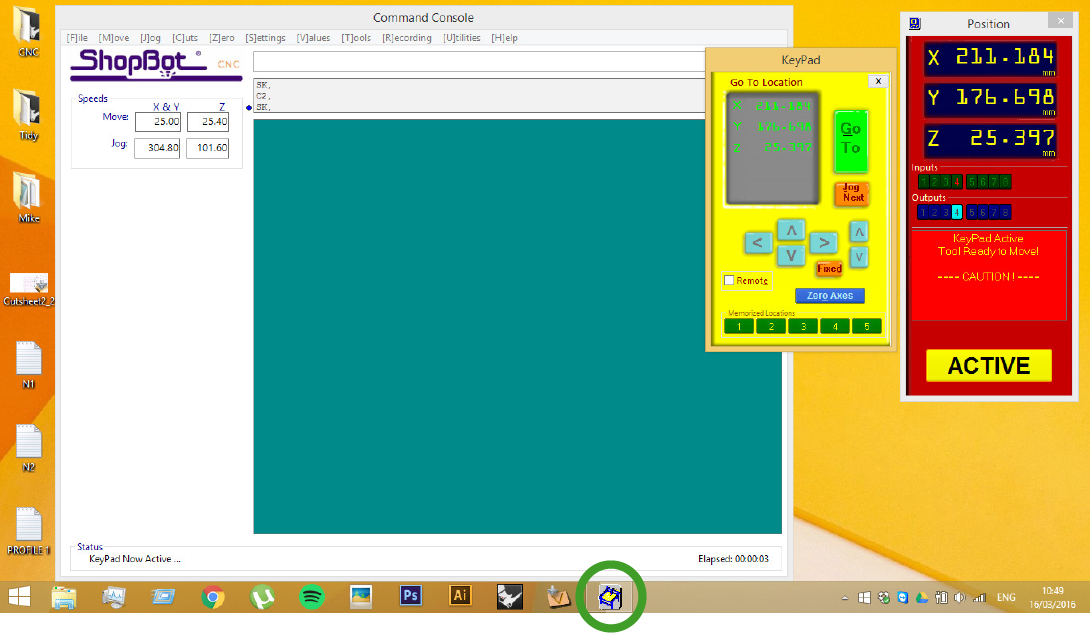
The SB3 program consists of a number of separate windows, as you can see above.
- The red panel shows the status of the machine, the coordinates of the tool, and the status of sensors and outputs of the control box. A few icons here let you do the most common actions.
- Click the yellow icon to show the control panel (or 'K' on the keyboard) and the basic move/jog controls. With the yellow panel open, you can use the arrow keys and `PgUp` and `PgDn` to move the tool vertically. Be aware not to crash the machine. `Up` moves the machine on its short axis and `Right` on its long axis. It is orientated the same way at the computer in the Fab Lab workshop.
- The green panel is a g-code console, and there is another dialogue box with the Spindle Control.
Loading bits and material
- Calibrate the X- and Y-Axis,
- Correct bit is in the spindle and secured,
- Material in place and secured,
- Calibrate the Z-Axis
- The dust shoe is clear of the moving parts and secured in place
Calibration, X- and Y-Axis
With the material now in place, let's first set up the X- and Y-Axes. You can re-do this if necessary, but once per job usually suffices.
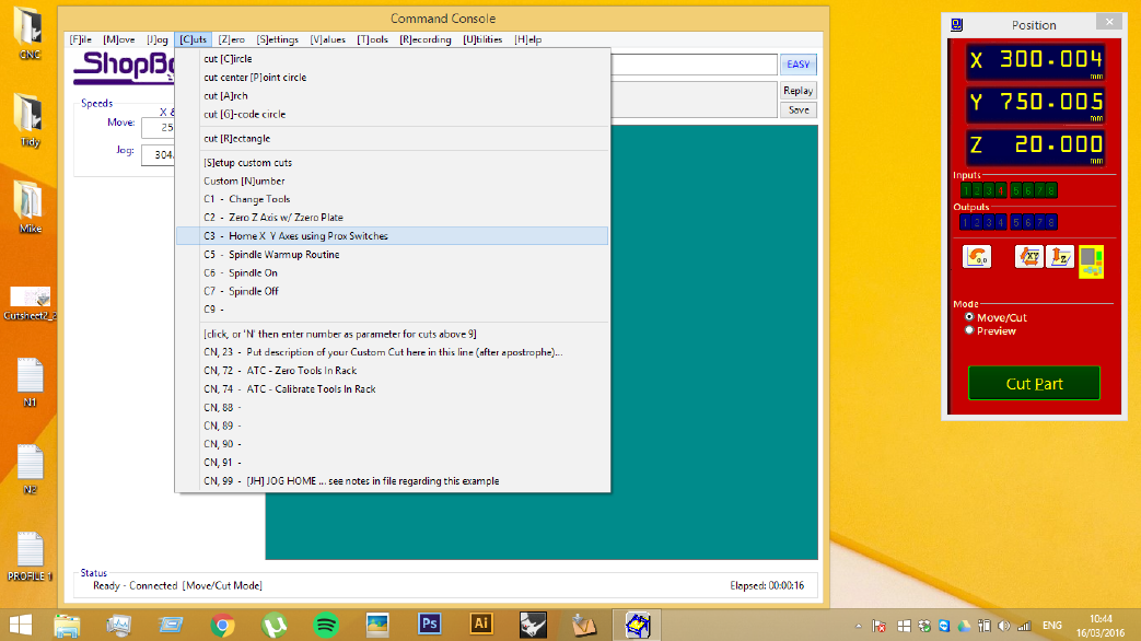
Go to [C]UTS in the file menu and C3 - Home X Y Axes Using Proxy Switches. Or type C3 or press the icon on the Red Panel with XY on the symbol - it's one of the square icons in the middle.
Important: The gantry will begin to move as soon as the routine is started. The gantry moves along the X and Y directions until it hits the proxy switches in both, giving an accurate and consistent home position.
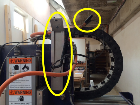
Changing the bit
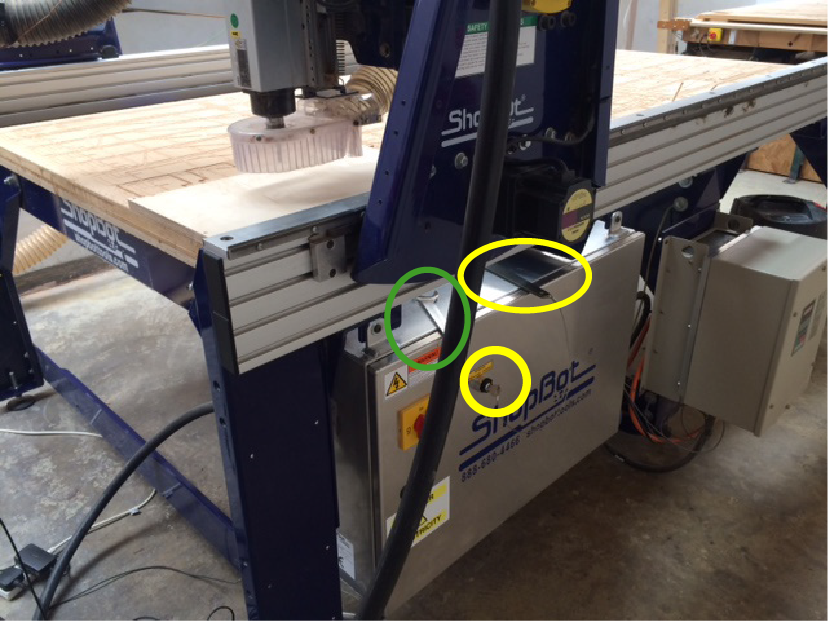
- Above, see the wing-nut for fixing the shroud.
- Use the socket/wrench to release the nut and drop the hood so you can clearly access the spindle.
- Take the tool (the one attached to the key) from the side of the control box and the wrench from the top of the controller box (yellow and green in the image below)
- Next, loosen the head of the spindle, as per the sequence of images below.
Note: If the key is not in place, the spindle will not spin. This is a safety feature to prevent starting in error while the machine is being adjusted.
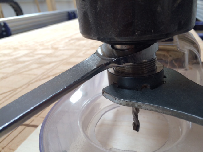
With the wrench(top) in your left hand, pull the two together in order to loosen the head. Pushing them apart will tighten the bit.
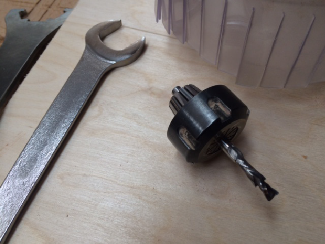
Loosen until the full head comes free and remove it from the machine.
There are 3 pieces to this, as seen above.
- Slide the bit out first
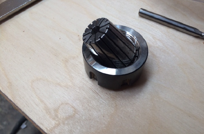
- The collet can then be popped out but pushing it to the side.
- Clean any sawdust from inside the collet, and change out this collet, if necessary for one that matches the bit diameter to be used.
- Reassemble without the bit, and thread onto the machine again. Slide the bit into position before tightening fully.
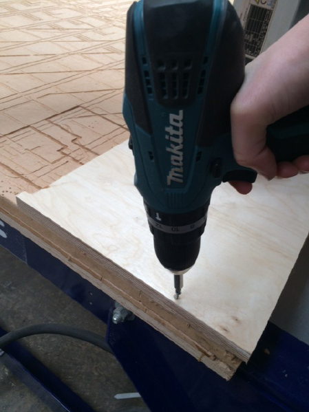
Fix the material to the bed.
As you have kept a 20 - 30 mm margin in your drawing keep your screws within this margin. See above.
On a full sheet, 4 screws might be adequate, but it is up to the machine operator to determine if more might be necessary to keep the material in place during the job.
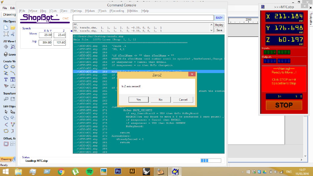
Calibration, Z-Axis
This process will allow us to easily find the top level of the material, needs to be done for different thicknesses of material and for each tool change.
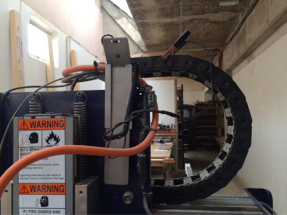
Remove the Plate and the Clip from their places above the spindle. There is a small current running when the two are in contact - this shows up as sensor 1 on the SB3 Controller.
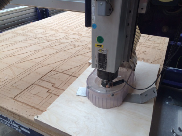
- Place the clip around the neck of the router, and the plate on the material and bit as shown in the image above.
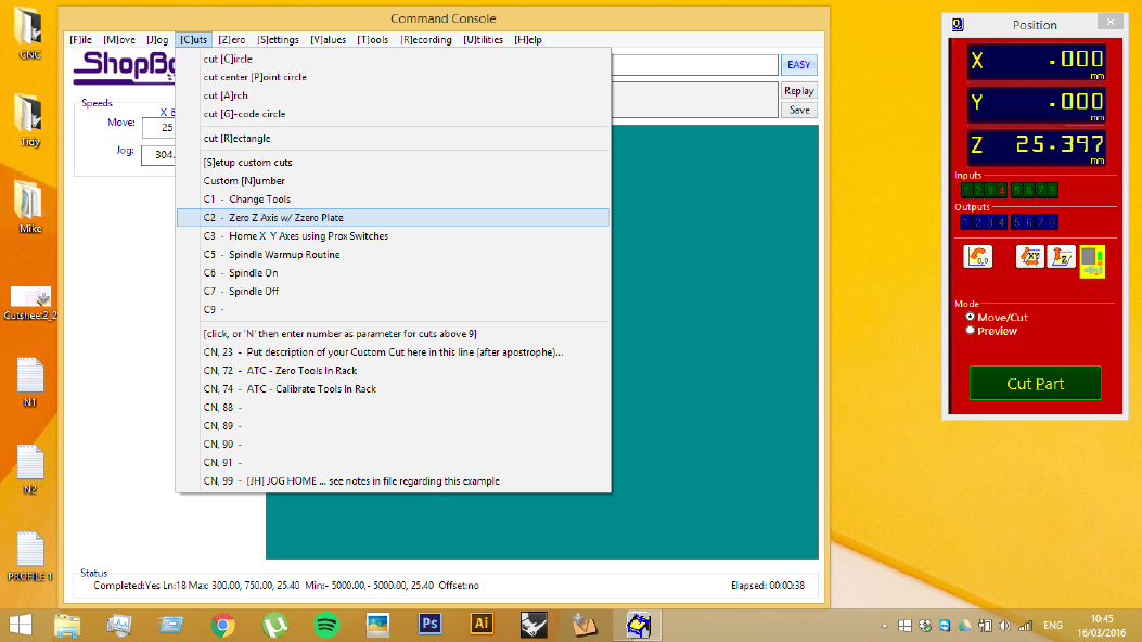
- Return to the computer and click
[C]UTSin the File Menu - Then select
Zero Z Axis with Zero Plates, or typeC2, or press the icon on the Red Panel withZon the symbol - it's one of the square icons in the middle.
- Finally check that both the clip and the plate are in place, if this is the case hit Enter and the machine will start the calibration routine.
- Once the head has plunged twice it the bit will be zeroed. Click
OKto confirm. - Ensure that the both the clip and plate are put back in their place
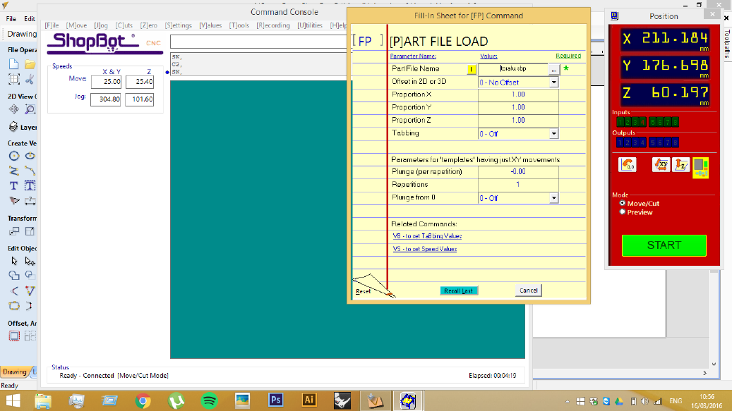
Sending a job to the machine
Once these steps have been completed, return to your drawing in V-Carve Pro
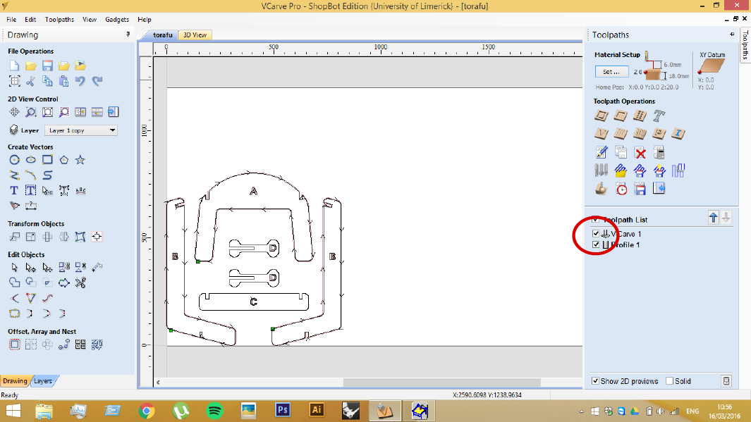
In V-Carve Pro, ensure that the correct toolpaths are selected on the right-hand panel. Once selected, we are ready to save them to their own G-code Part File - the icon to save toolpaths is circled in red below.
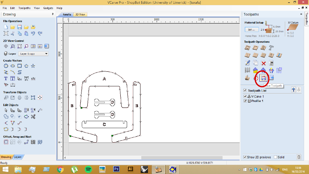
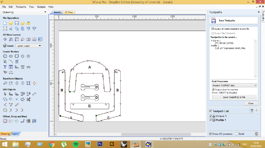
- When you click this icon, the right-hand panel will list all toolpath a little information, ie tool number and toolpath name. If these are correct simply click
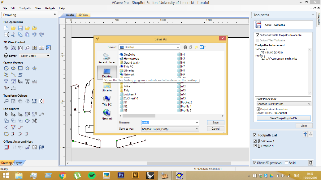
Save Toolpath(s) to File. - If
Output to machineis checked - this will start opening the file directly in the ShopBot program. This is the default, and usually preferable.
Note: Make sure that you do not save the file to a usb - as it make get accidentally removed, or may not be read fast enough throughout the job
Running the job
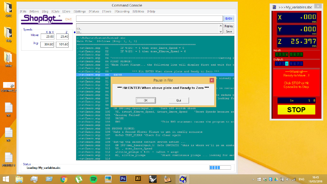
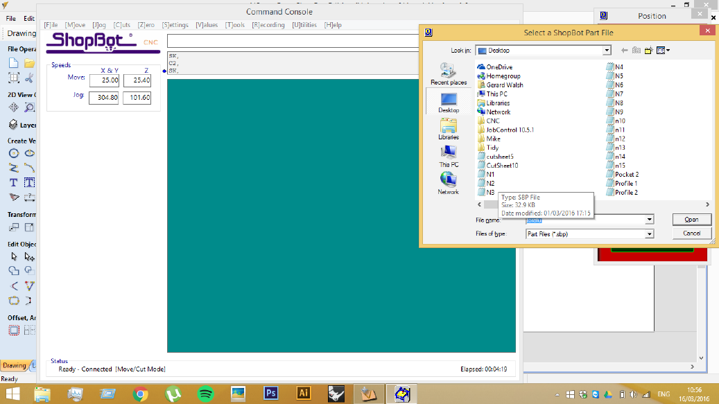
Running the ShopBot3 Controller software
- Confirm the correct file is selected, simply hit
EnterorOpen - The details of this file will then open and the screen below will appear - Hit
Enteragain, to run the file
- Some final checks may appear if the bit has been changed since the previous job. If you have the correct bits in the machine, just press
Yes. (Otherwise, it's generally easier to cancel, make any of the preparations you missed, and reinitialise the job as per the instructions for Outputting directly from V-Carve Pro above)
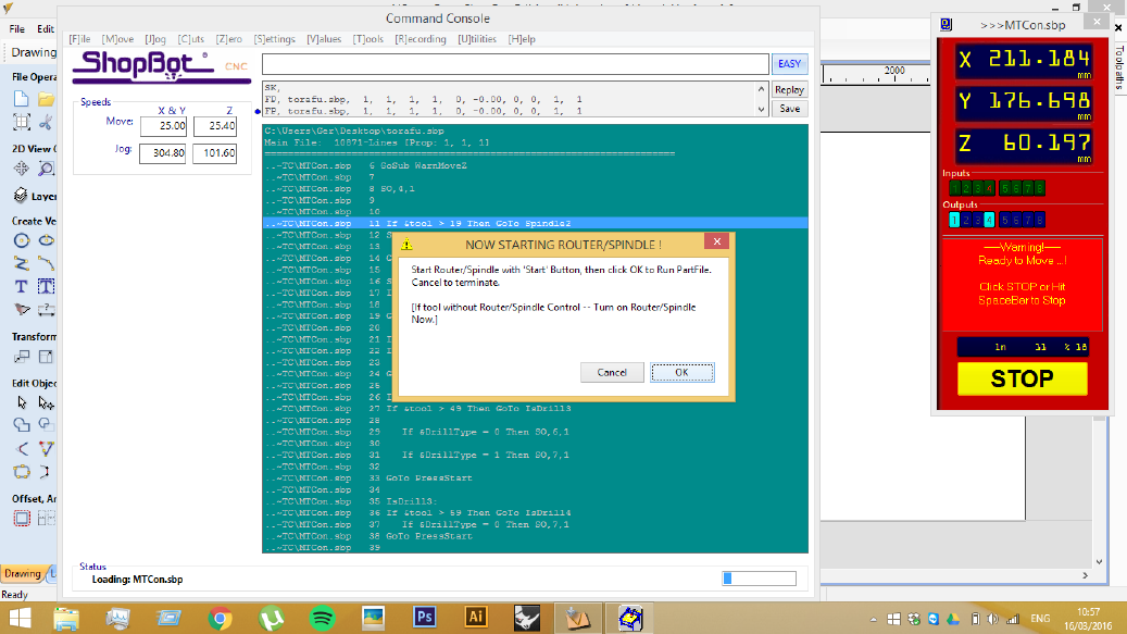
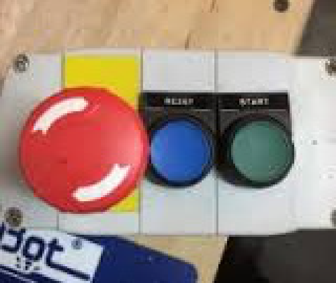
Finally you will be asked to turn on the spindle. Before pressing ok on this screen, push the green button shown in the below image. This will start the spindle spinning.
Ensure that you (and anyone else in the workshop) are wearing the appropriate safety gear. And observe all due caution while the machine is in operation. Turn on the Extractor.
Note: If the spindle does not begin spinning when you press the green button, it may be that you have not returned the key attached to the tool in the control box. Unfortunately, this freezes the program, and it will be necessary to reload the Part File.
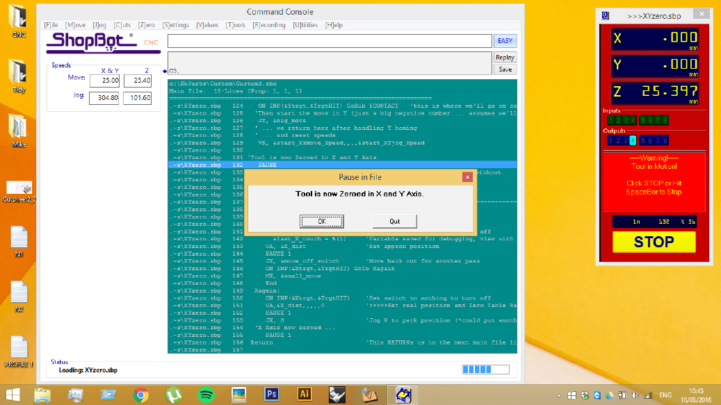
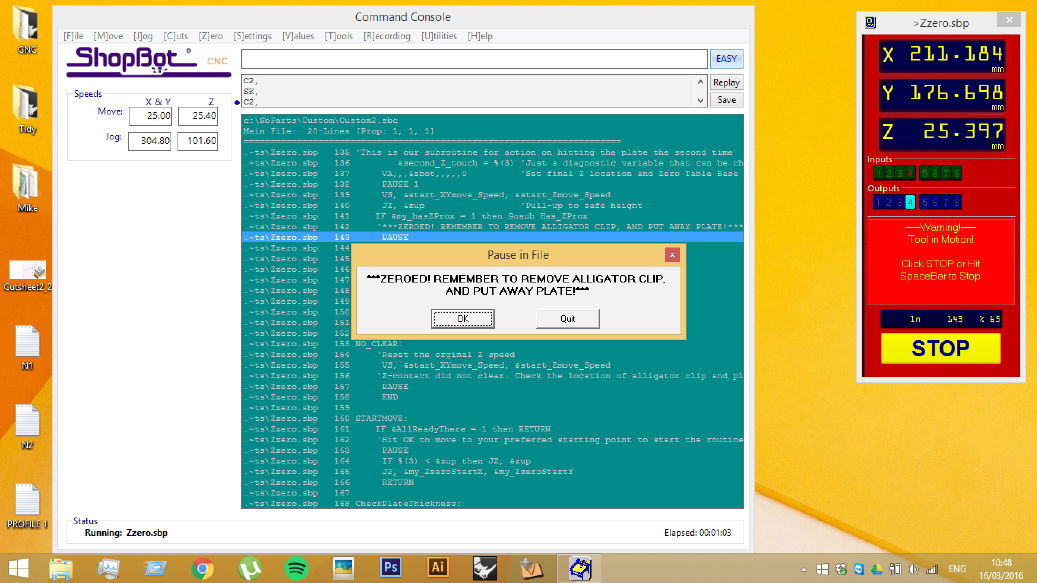
Once the Spindle has engaged, press OK on the screen and the Part File instructions will start. The machine will first move to the home position, and then start the job.
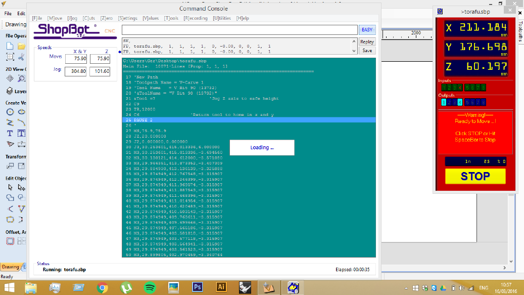
Your final screen (Loading...) will appear something like the screenshot above, g-code on the green panel, the current position, and the % completed on the red panel.
- If at any time you wish to pause the job simple hit the Stop button, or Space on the keyboard - this gives the opportunity to safely inspect the machine or the piece without having to start over.
- In the case of an emergency, hit one of the two emergency stop buttons - one located on the gantry; one located next to the green power button for the spindle.
- Do not leave the machine unattended while it is in operation.
- If at any time you are unsure about anything covered in this document, just ask a member of staff to help before proceeding.
AFTER YOU ARE FINISHED!
As with any shared workspace it is essential to use the space in a way that does not cause harm or undue labour for others. When using the router in the Fab Lab we ask that you:
- Are efficient with your use of material
- Leave the workspace clean and tidy, as you found it
- Any offcuts need to be cut down, so that they can be kept, recycled or disposed of. This may require using the circular saw, which requires that you are suitably inducted for such tools by Fab Lab staff and competent on that tool.