1. Blink Sketch
Download the Arduino IDE Software (current version 2.3.7) from their website.
* Fix 1: Attention ESP32/Firebeetle users!
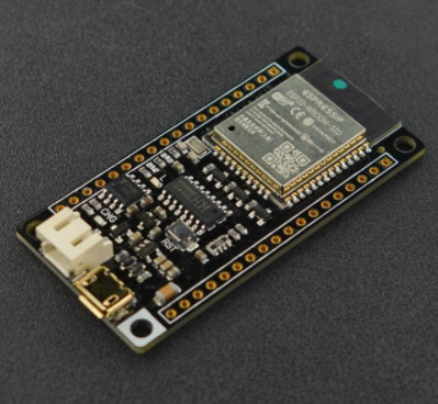
"DFRobot FireBeetle series is the low-power consumption micro-controller intentionally designed for Internet of Things (IoT) projects. FireBeetle Board - ESP32 integrates a Dual-Core ESP-WROOM-32 module, which supports MCU and Wi-Fi & Bluetooth dual-mode communication. The FireBeetle is powered by USB or 3.7V external lithium battery. The Lipo battery can be charged directly by USB and external DC."
You have to add an additional link to the boards manager. Go to File > Settings (Windows/Linux) or Arduino IDE > Settings (macOS).
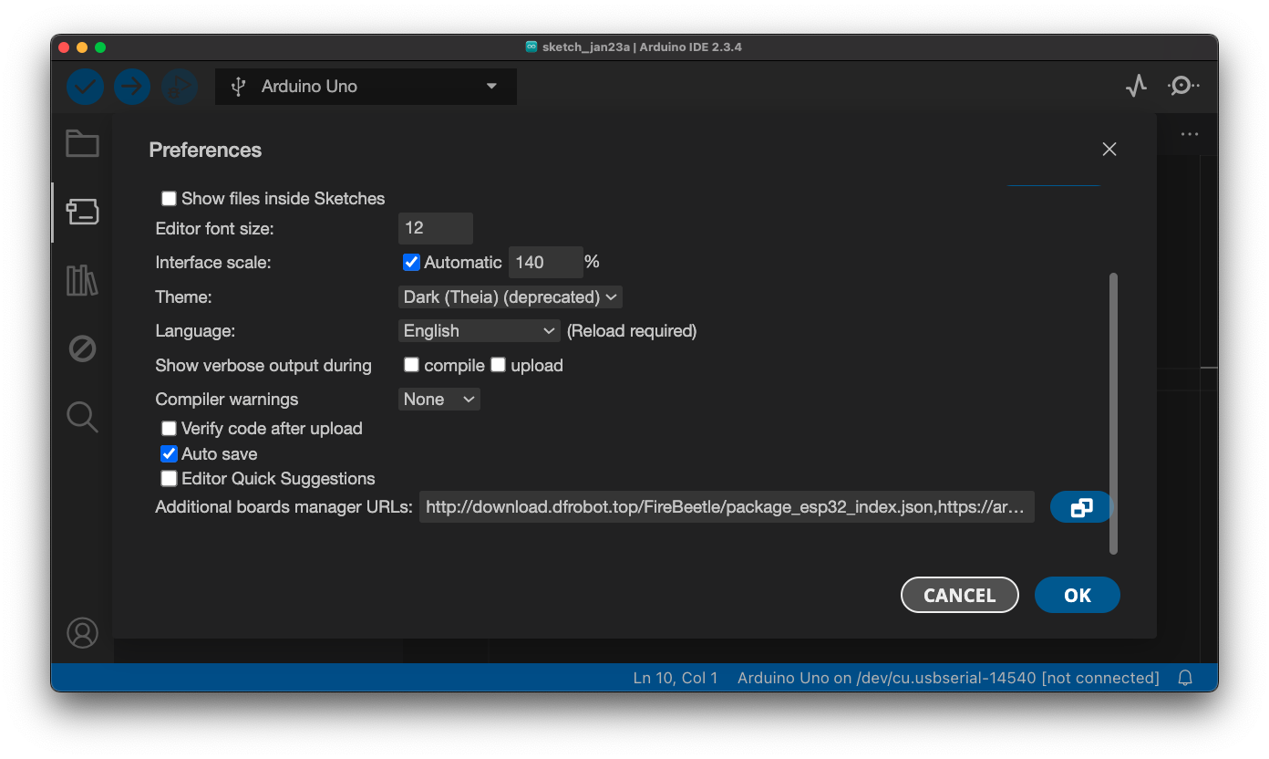
Add this link: https://downloadcd.dfrobot.com.cn/boards/package_DFRobot_index.json

* Fix 2: If you're using an Arduino Nano, or what might be an Arduino clone board...
You may need to download and install the CH340G driver.
Follow this tutorial (from the DFRobot wiki) or this tutorial (from SparkFun, more general) and download the driver for your respective operating system.
* Fix 3+: Board Manager still not loading Board Definitions?
- Option 1: Use generic ESP32 board definitions (The one from Espressif should be fine. Some advanced DFRobot-specific things).
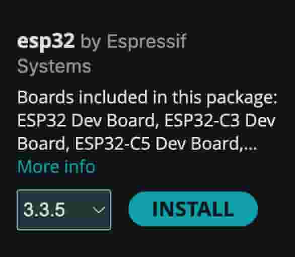 In the board selection, described below, you should select `ESP32 Dev Module` instead.
- Option 2: Use Platformio instead. PlatformIO is an alternative _development environment_ for microcontrollers that is more recent. It is more advanced, but may be more likely to get your ESP32 board working. PlatformIO runs inside VS Code and works on macOS, Windows, and Linux. Try this 10 minute tutorial and easier 4 min tutorial
- Option 3: Extend the timeout, to allow the download more time to complete.
- Option 4: Download directly, and add to Arduino IDE.
Opening up the Arduino IDE
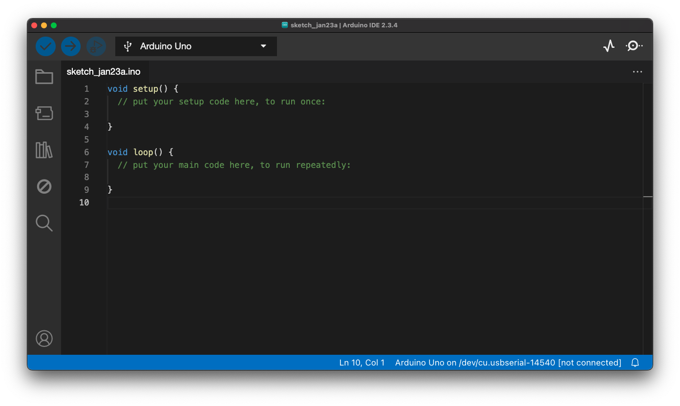
Go to File > Examples > Basics > Blink, and it will open the following:
const int LED = 13; //this is pin `IO13` or `D7`

//setup runs once, when you power on the board
void setup() {
  // initialises LED pin as an Output
  pinMode(LED,OUTPUT);
}

// loop runs over and over
void loop() {
  digitalWrite(LED,HIGH);
  delay(1000);
  digitalWrite(LED,LOW);
  delay(1000);
}
* Your sketch may have "LED_BUILTIN" which works the same, but points to a built-in LED that is included on the board.
Let's wire everything up before uploading.
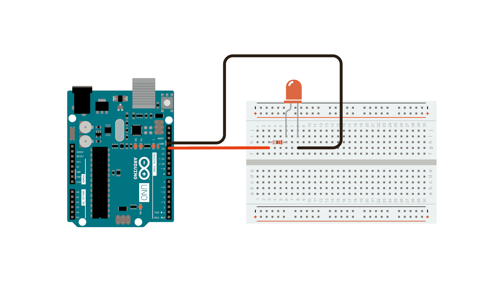
Wiring
From your documentation, find a diagram, similar to this one. Orientate your board according to this diagram. Pins are sometimes called IO's or GPIO Pins, general purpose input output. The board may have the short names, refer to this image for other functions.
Some pins are special.
D0,D1, etc. Digital in and Digital out.- some digital pins may be marked with
~. None are shown on the FireBeetle pinout, documentation says all pins are suitable forPWM(Pulse-Width Modulation). A0,A1, etc. Sent to an Analogue-to-Digital converter chip, returns a value out of 1023 or 4095.SCK,SCL,MOSI/MISO,SDAare youri2cconnections. And other tags are used to denote pins used for other protocols.

Pinout diagram for ESP32 FireBeetle
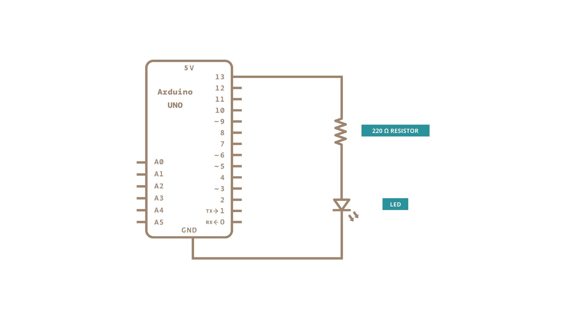
Wiring and Schematic
Uploading your Sketch
The buttons at the top of your sketch, are Verify, Upload, Save and Load and there is a dropdown that allows you to pick your board and model. On Windows, this may say Arduino Uno on COM3 for instance. The first time you use it, it may say Unknown instead of the board name. The pop-up looks like:
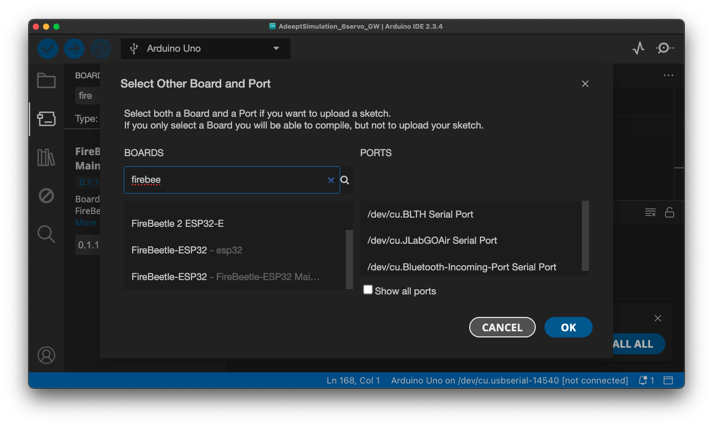
And...
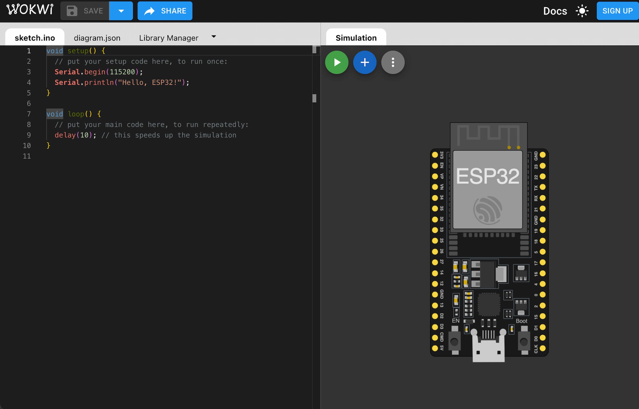
Note: There are programs that allows you to simulate circuits, like Wokwi and TinkerCAD. It simulates, not only your electric circuits, but also the code running on the board.
...Next
Let's try an example, like this HTTP Server to control some local LEDs on Wokwi or this Soil Moisture sensor on DFRobot's forum. And there are examples built into the Arduino IDE, and there are examples with each library you install (use the library tab on the left).
Note, examples may use different boards, or diffent ESP32 variants. Follow the Pinout diagram from your documentation to ensure you've connected it and coded it for the board you have. If you are including a library, make sure that it is compatible.