Introduction to CNC cutting
v0.6 by Ger Walsh - August 2023
This is a guide about CNC Cutting and using the ShopBot CNC Router. If you have not received the Induction on the machine, including the Health and Safety presentation for the machine, you may not use this machine. Please refer to our workshop safety information in regard to using the CNC router.
The Shopbot is a factory-built CNC Router able to cut wood, plastic, foam, composites and some soft metals. Maximum material size: 2440 x 1220 x 150mm. Many different sizes and types of cutting bits can be used.
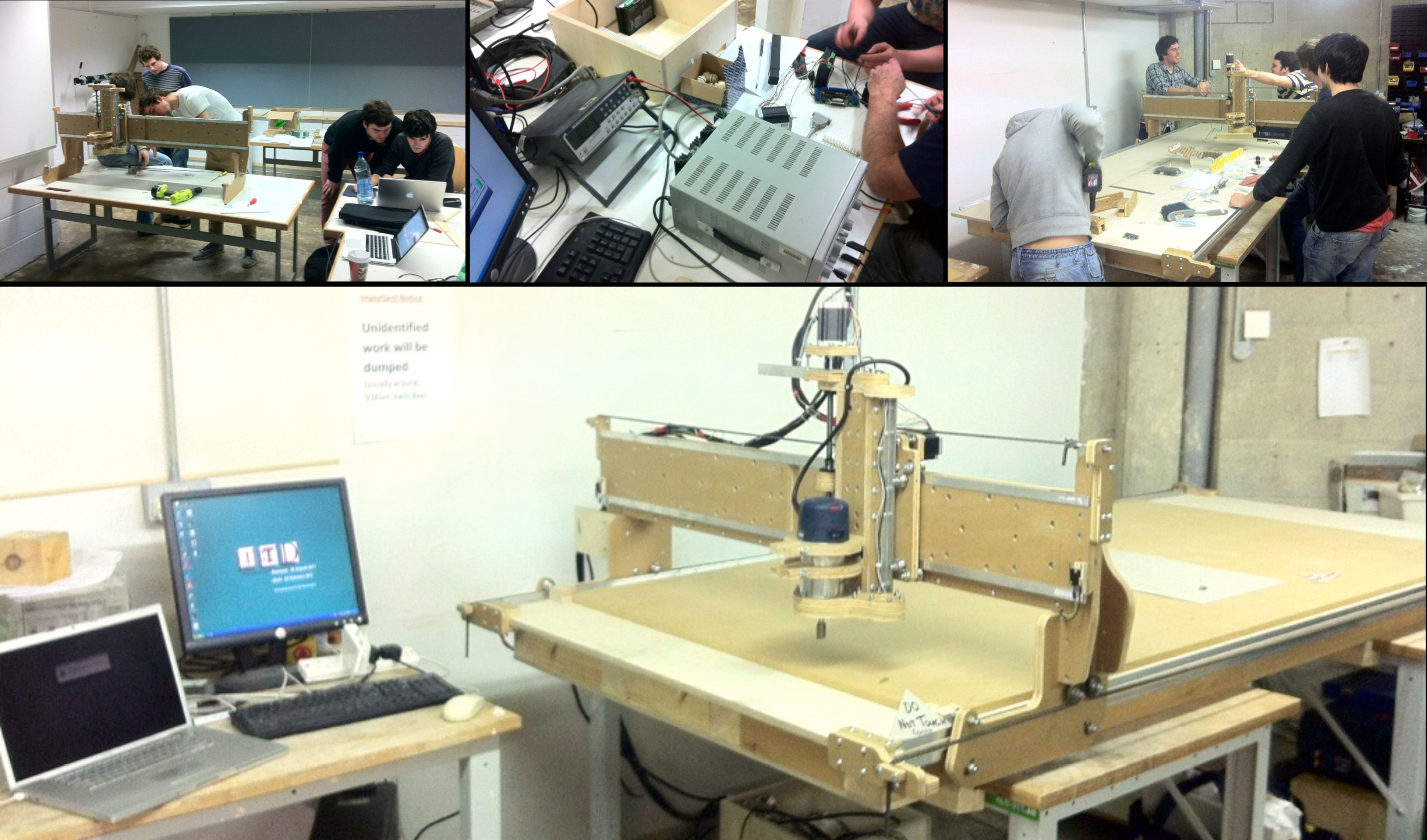
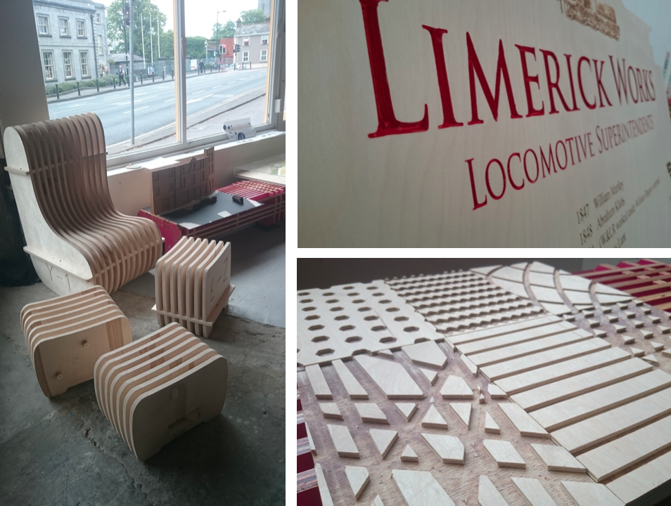
Blackfoot CNC, at DIY kit, built in SAUL, Limerick 2011
Steps
Prepare your Design with a CAD program - AutoCAD, Solidworks or similar. You can use 3D files (like .STL, .3DM or .STEP), but this machine is only a 3-axis machine, meaning that it can do some kinds of 3D work but not all.
Use a CAM program to prepare your job, eg. V-Carve Pro, (On other machines, this may be a program like AlphaCAM or similar)
1. CAD (short for Computer Aided Design)
Files can be prepared in programmes like AutoCAD, SolidWorks, Fusion360, FreeCAD, DraftSight, and even Adobe Illustrator and Inkscape. It's possible to draw directly in V-Carve Pro.
For now, we want CAD files in .DWG and .DXF formats, bitmap images for some engraving functions (.JPG, etc.), or 3D .STL files.
* Some programmes combine the CAD and CAM steps, eg., Fusion360 from Autodesk and SolidWorks through SolidEdge. (To do this, ask someone in the lab. You will want to find out if your program has a "Post-Processor" for a "Shopbot PRSAlpha 9648")
CAM (Computer Aided Manufacturing)
For this step, we use a software called V-Carve Pro, which is made by Vectric.
CAM software makes ToolPaths from your drawing, and exports in G-Code format.
Most 2D work can be achieved a combination of Profiles, Pockets, Drill Hole Pattern, or V-Carve Profiles.
Your G-Code file (.SBP in this case) contains multiple Toolpaths.
And each Toolpath contains settings like feed rate (horizontal speed), spindle rate, cutting/pass depth(mm), and the path for the tool to follow. More details under 'Toolpath Parameters'...
We're going to send our file with the Shopbot Controller (SB3).
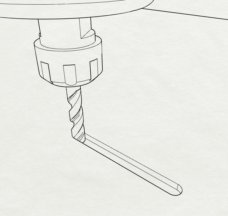
Bits
Some of the typical bits used for CNC routing:
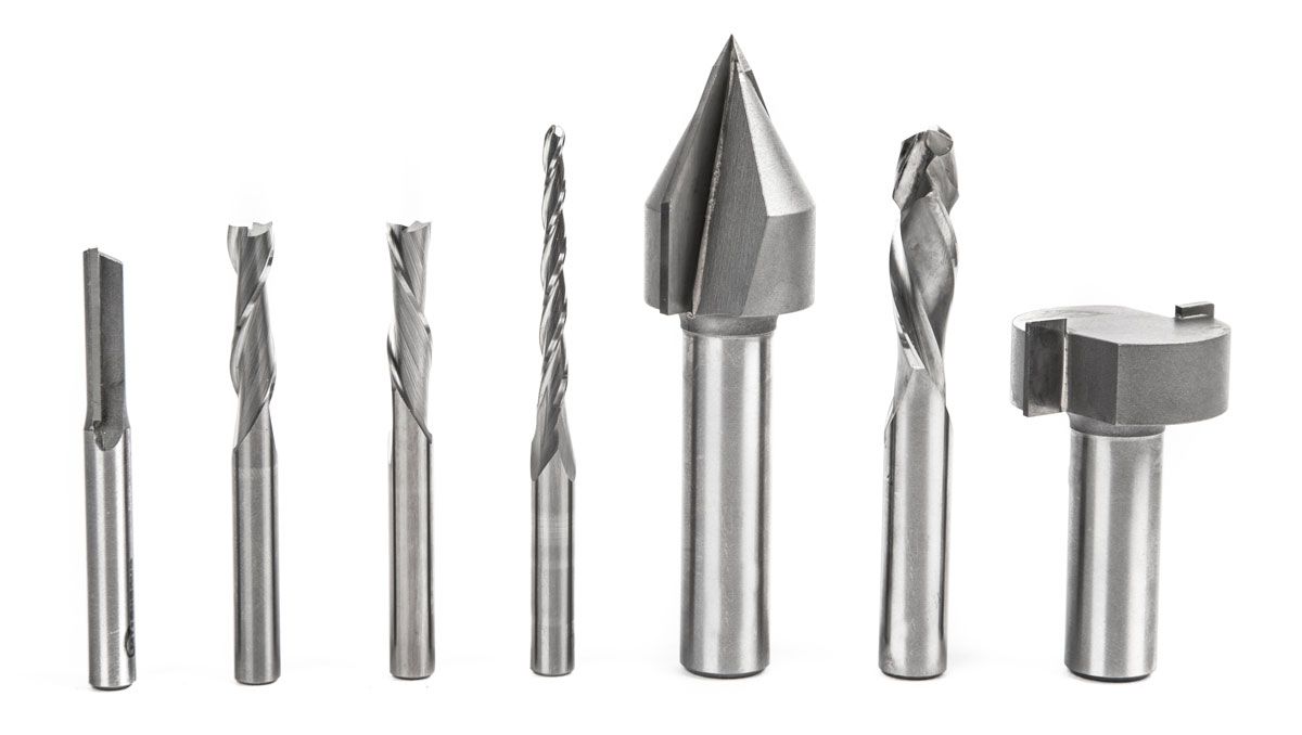
image Luis Rodriguez, Make Magazine
Choice is based first on material(engineered boards, solid/hard timber, soft/hard plastic, metal), then on application (are you cutting through? Are you carving letters or doing 3D profiles?).
For example, a good choice for timber and engineered boards, generally, would be to use
- a Compression Bit for outside profiles(the 6th tool in the image above),
- a Downcut Bit for pockets (number 3 above),
- and a V-bit for V-carving letters(number 5 above).
You can use roundnose or roundover bits for flute-shaped channels and fillets. V-bits also make good chamfers, and are available for various angles. Small-tapered roundnose bits are good for 3D finishing work.
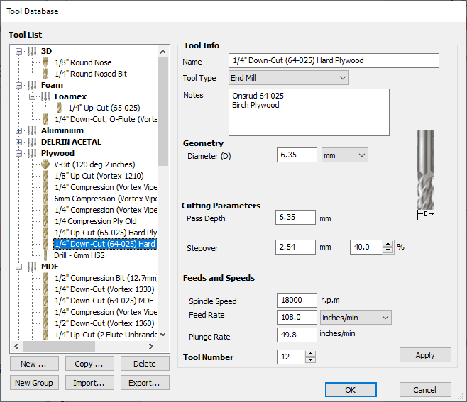
Programs like V-Carve Pro, store commonly reused values, like feed-rate, pass depth and so on in their Tool Database. You can find settings from the tool manufacturers themselves, like cutter-shop.com, Onsrud. Use of a Tool Database makes it easier to get started. Typically setting are given in ranges that you can adjust as you get more familiar with them.
There is a download link to our tool database on the V-Carve Pro page.
Luis Rodreguez has a good article on this, if you want more information: article.
Toolpath Types
SeeToolpath Parameters below for each setting.
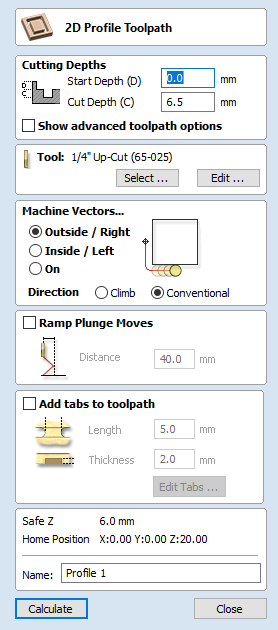 Profile
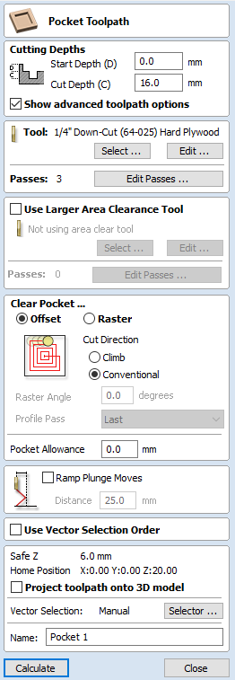 Pocket
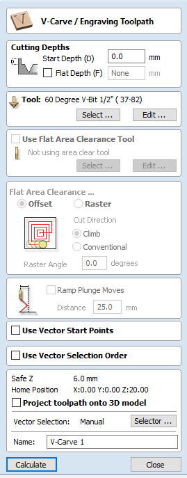 V-Carve
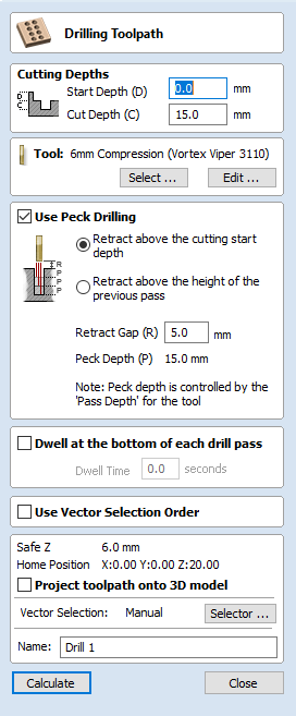 Drill Holes
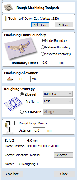 Roughing (3D),
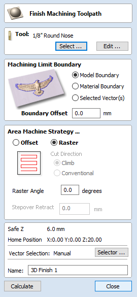 Finishing (3D)
Tool parameters
Tool Type can be set to "Ball Nose", "End mill", "V-Bit", "Engraving", or a number of others. This determines other properties that can be entered under "Geometry" - chosen preset from tool database.
Diameter is Diameter. (Angle, Taper, and other options will appear here for other types of tool).
Feed Rate (ips or mm/s) is how fast the tool is allowed to move horizontally. If changing to other units, note that it does not recalculate the other
Feeds and Speedsfor you.Pass Depth is the maximum allowable depth that the tool can cut into the material. A good rule of thumb is the same as the diameter. If you are cutting 15mm material with a Pass Depth of 6.35mm, your first depth will be 6.35; then 12.7, then 15mm, and so your toolpath will contain three "passes".
- Also Start Depth, if you have already removed some material where you are cutting.
Plunge Rate is how slow or fast it moves vertically in material.
Spindle Speed is given in revolutions per minute, rpm.
Stepover is how much overlap there is if trying to cut out a shape. Can be specified by distance or %. Relevant for Pocket profiles or 3D Roughing paths.
To see more about Tooling & Tool Databases see: this video from Shoppbot Tools Ltd (external link to YouTube.com).
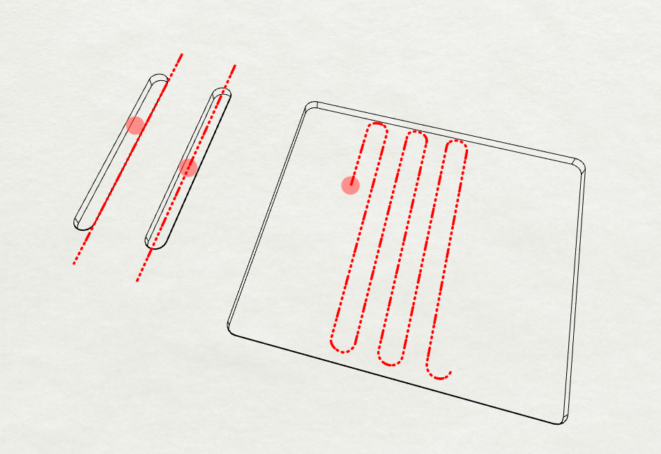
- Tabs. Tabs are breaks in profiles or 3D work so that nothing moves around while you work. Enable on your Profile cuts, and click
Edit Tabsfor options to place them.
Advanced toolpath settings:
- Choose Inside/Outside/On (works best with closed Polylines, may be inconsistant otherwise),
- Direction (Climb or Conventional, clockwise or anti-clockwise), and Ramping (if you want to start above the material and),
- Clearance or Roughing/Finishing Strategy (Offset, Raster, 3D Raster along Y direction),
- Clearance Tool (A second, bigger, tool to help clear large areas more efficiently),
- Pecking and Dwelling (to do with Drilling paths),
- Boundary Limit (Like cropping your 3D model).
Advanced File Settings.
Set these when you open a new file, or by clicking this icon,  , on your tool pallet (top left). For example:
- Material Dimensions,
- Safe Height,
- Origin/Offset.
Chipload (optional)
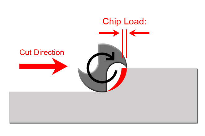
Often the settings you find online, will give you a range of values, or else they will give you something called "Chipload". You can think of Chipload as the amount of material removed by each turn or swipe of the cutter. There is a formula, which will help you figure out the above values based on the Chipload given.
Chipload = Feed Rate / (RPM x no. of flutes)
...where "Feed Rate" is in inches per minute and "RPM" is revolutions per minute. Some CAM programs will have a calculator for this built into the software. There are some softwares online that can help, but as long as you use the correct units, you can use this formula yourself.
Online Resources
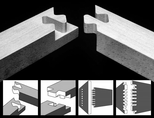
50 Digital Wood Joints: an open source collection of designs for CNC cut timber joints (license: CC BY-NC-SA 3.0 Jochen Gros)
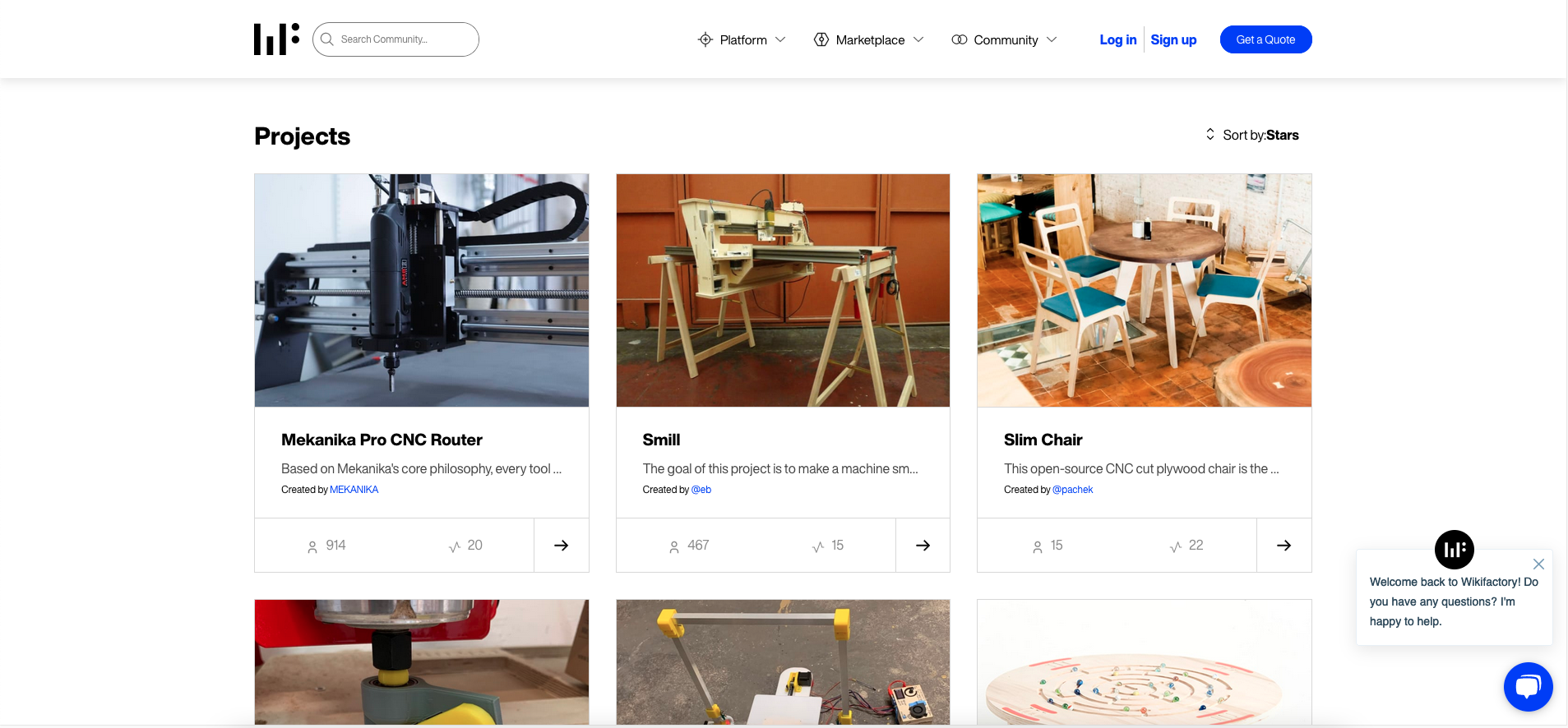
Wikifactory.com is a product development platform, and also provides the platform for projects.fablabs.io.
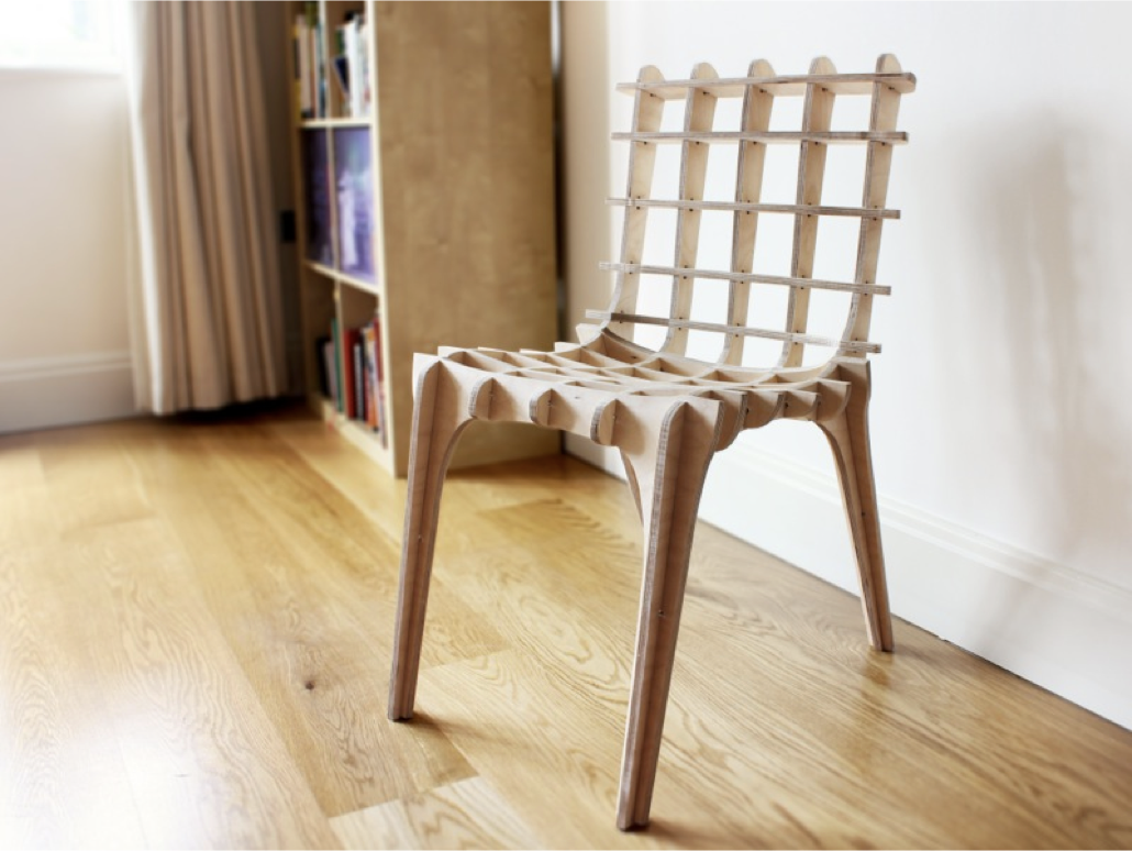
sketchchair.cc is an open source project, supported and developed by a number of contributors. SketchChair is designed to give anybody the opportunity to design a unique one-off original chair that is personal to them. Any of the chairs featured on the site are freely available to be downloaded and edited by anybody, allowing chair designs to evolve as users continually refine and modify them.
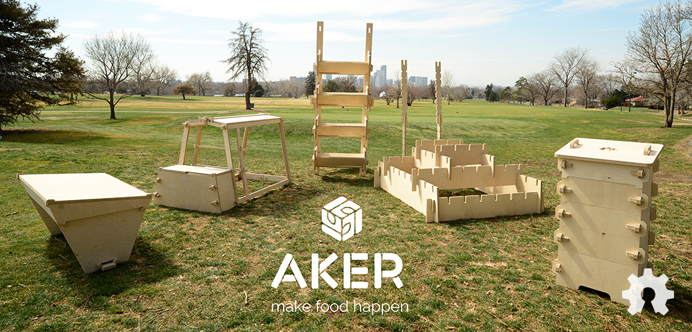
AKERKits are another resource for downloading great designs, this time with a focus on urban gardening, growing units, and beehives.
Download: https://github.com/AKERKits/AKERKitSourceFilePacks
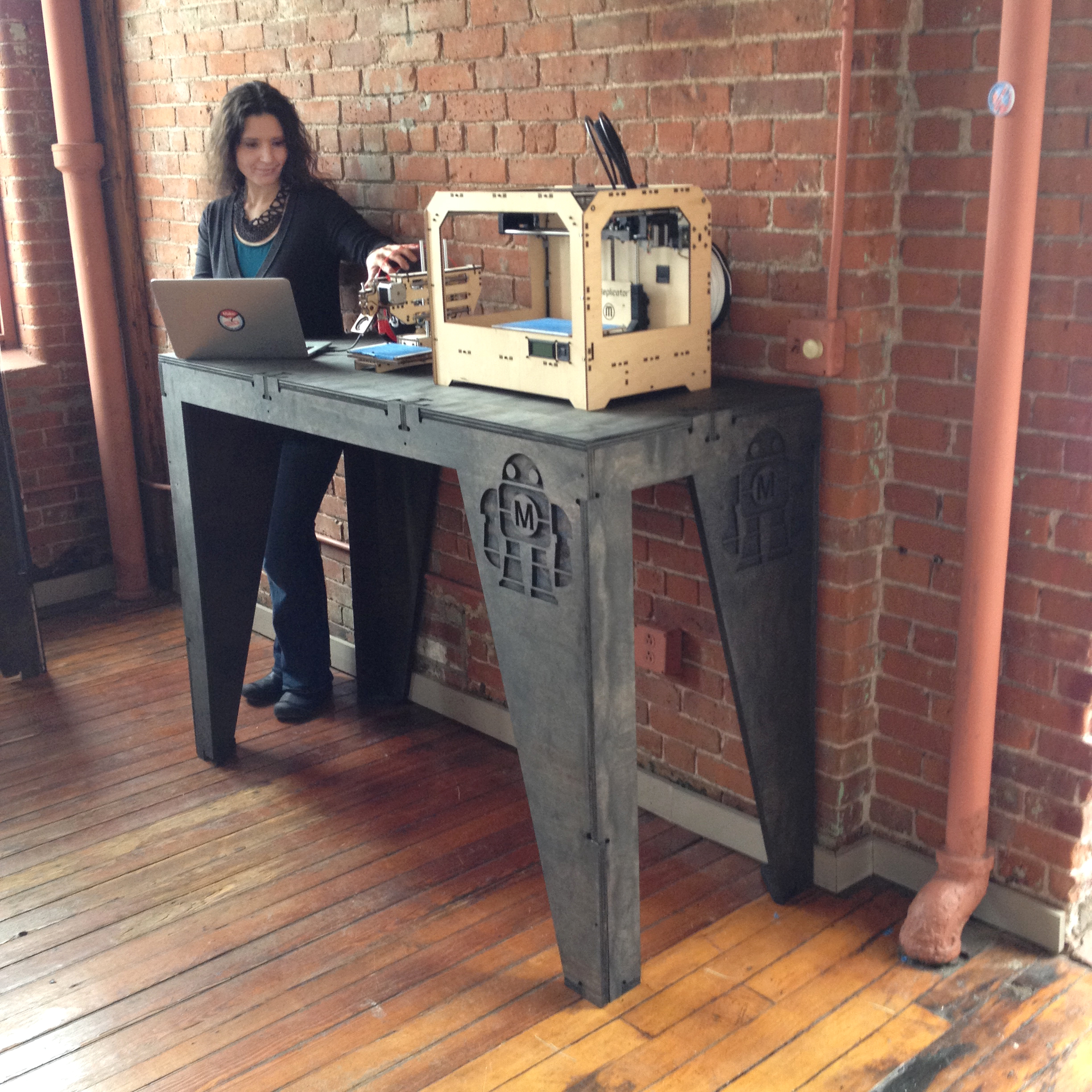 Maker Bench Made with a CNC Router is an article from Make magazine. It shows the whole process from design (using custom parametric software), material selection, cutting.
More Examples:
- AtFab by Anne Filson and Gary Rohrbacher.
- The Italic Shelf by Ronen Kadushin
- The Layer Chair by Jens Dyvik.
- The Alex Chair by Alex Zhang - and many more designs from Obrary!
- Shaper Hub
- Youtube channels for Vectric Ltd and Shopbot Tools.
- AKER Kits repository
- Open Source Beehives
- Shaper Origin (also Maslow CNC and Yeti Smartbench)
- Take a look at our tutorial on Visualising G-Code
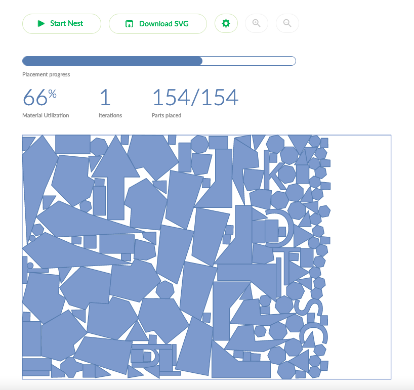
- SVGNest.com, (also DeepNest and OpenNest - grasshopper plugin)