V-Carve Pro (v8.5) step-by-step
v0.1 by Gerard Walsh - 2016
VCarve Pro is a CAD/CAM software for use with Fab Lab's ShopBot Router developed by Vectric.
Please note, this tutorial is about V-Carve Pro version 8.5. V8.5 is installed on the lab computers, and an installer for this version is available for your own computer - it is a Free Trial for 30 days - just ask one of the staff.
This is windows-only software unfortunately. If you don't have access to any windows device you can use one of the PCs in the lab with it already installed of course.
CAD/CAM (computer-aided design and computer-aided manufacturing) refers to computer software that is used to both design and manufacture products. CAD is the use of computer technology for design and design documentation.
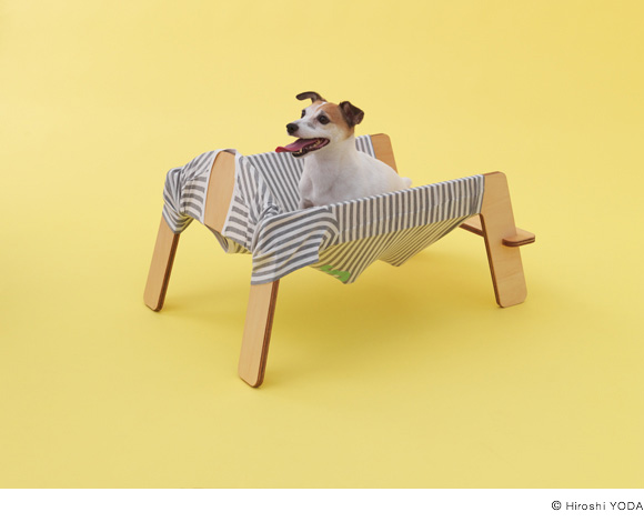
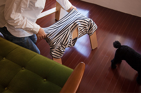
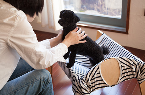
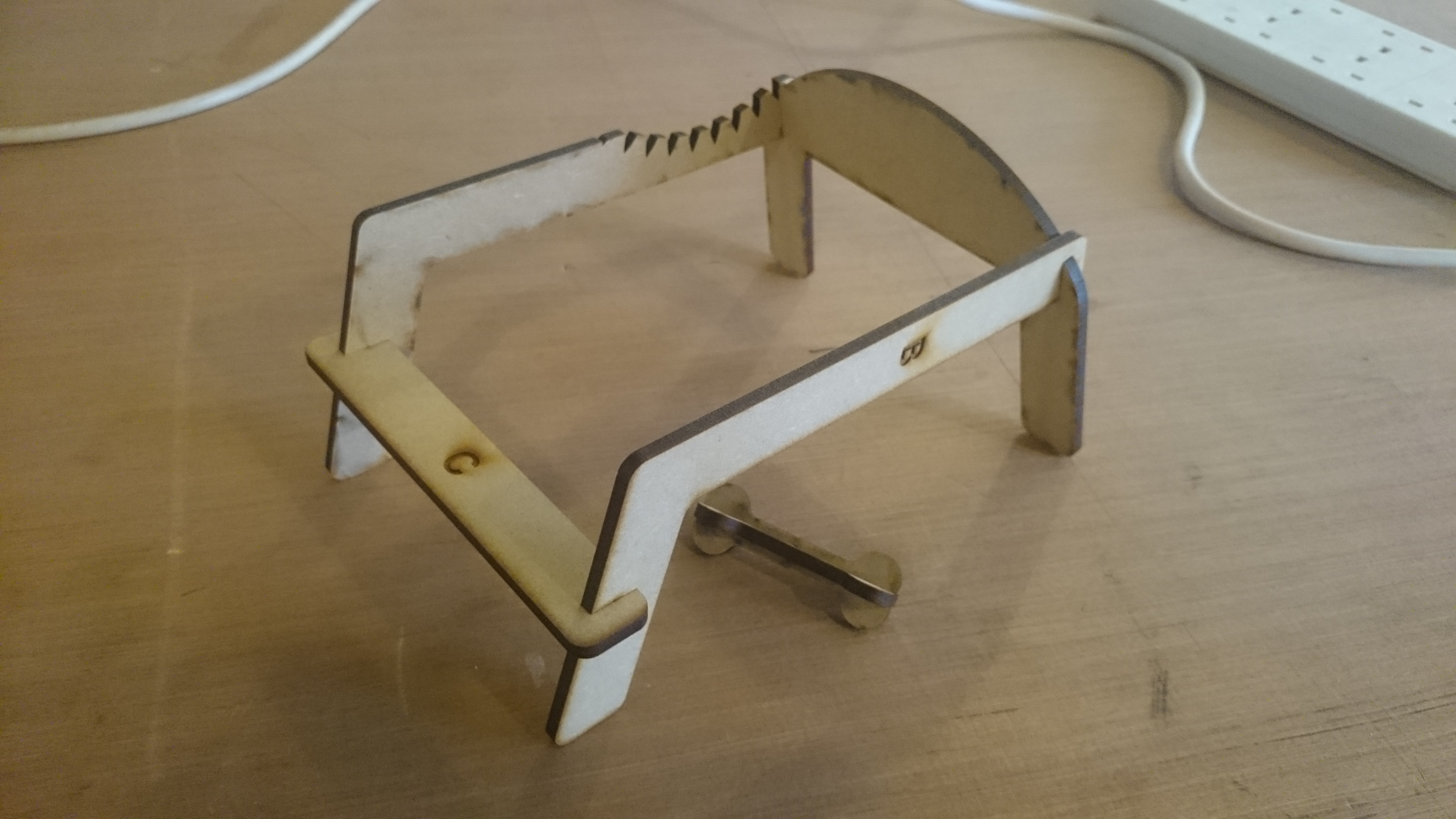
For the purposes of this tutorial, I am going to use the WANMOCK by Torafu Architects which is designed for a Jack Russell Terrier. This design, and indeed many others, are available for download or purchase on https://architecturefordogs.com
Steps:
- 1, Exporting form Illustrator
- 2, Opening VCarve Pro
- 3, VCarve Pro Basics
- 4, Layers in VCarve Pro
- 5, Adding Fillets
- 6, Adding a Profile Toolpath
- 7, Making a Pocket Toolpath
- 8, Generating Previews
- 9, Making a change to a Toolpath
- 10, Calculation etc.
- 11, Exporting Toolpaths
1, Exporting from Illustrator
Many resources that you download from the internet, will provide the drawing in .DXF or .PDF formats. I extracted the downloaded .ZIP file and opened the drawing in Illustrator.
Incidentally, this is a scaled 1:6 model from the laser cutter:
2, Opening VCarve Pro
Click Open an Existing File, and choose the file in the dialogue box. Enter the settings in the Job Setup screen:
The default setup is as follows:
- Job Width to 2440mm,
- Job Height to 1220mm,
- Set the Material Thickness (In this example, 18mm),
- Uncheck the Use Offset option,
- Make sure that the
XY Datum positionis set to the bottom left as shown, - The units are in
millimeters, - And you have not selected
Scale design with job size.
When set up, click OK.
3, VCarve Pro Basics
In general, the layout of V-Carve is as follows. Tools that have anything to do with editing or modifying your drawing are located on the left, and tools for the making of toolpaths are on the right-hand-side (hidden by default - just hover your mouse over where it says "Toolpaths").
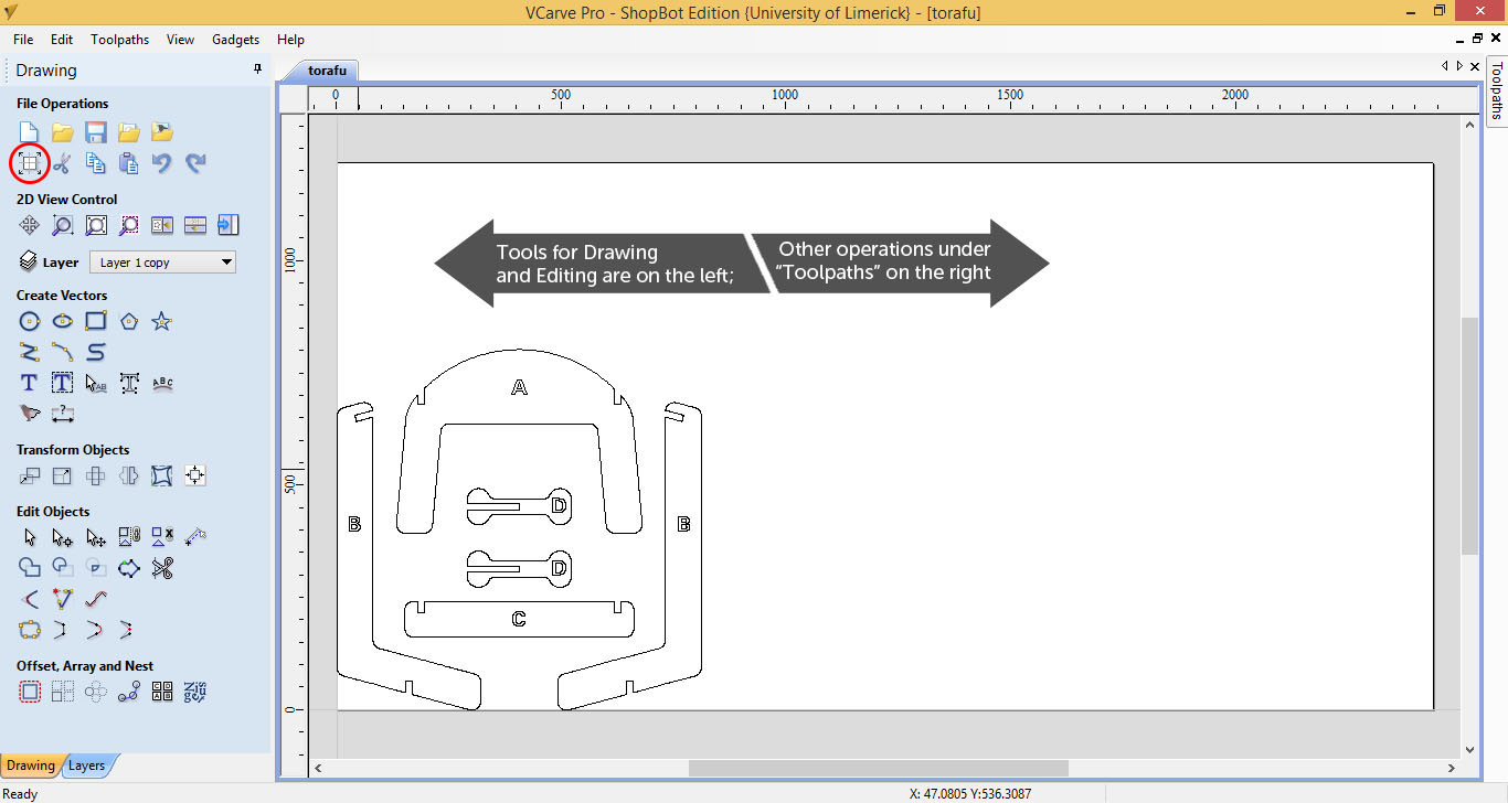
Note: You can access the Job Set-Up Screen again any time using this icon on the left - circled in red above.
On the left there are many tools for creating vectors - for example the rectangle tool, which is used as follows. In this animation, I'm adding a rectangle from 30,30 to 2380,1160. This rectangle represents the 30mm margin, drawn for demonstration purposes.
Under Transform Objects, click Move. As shown, you can then move your geometry inside the margin: +30 on the X Position and +30 on the Y Position.
4, Layers in VCarve Pro
On the bottom left, switch from the Drawing panel to the Layers panel. These come through from the file you've imported, and keep the names, colours and order assigned in AutoCAD or Illustrator.
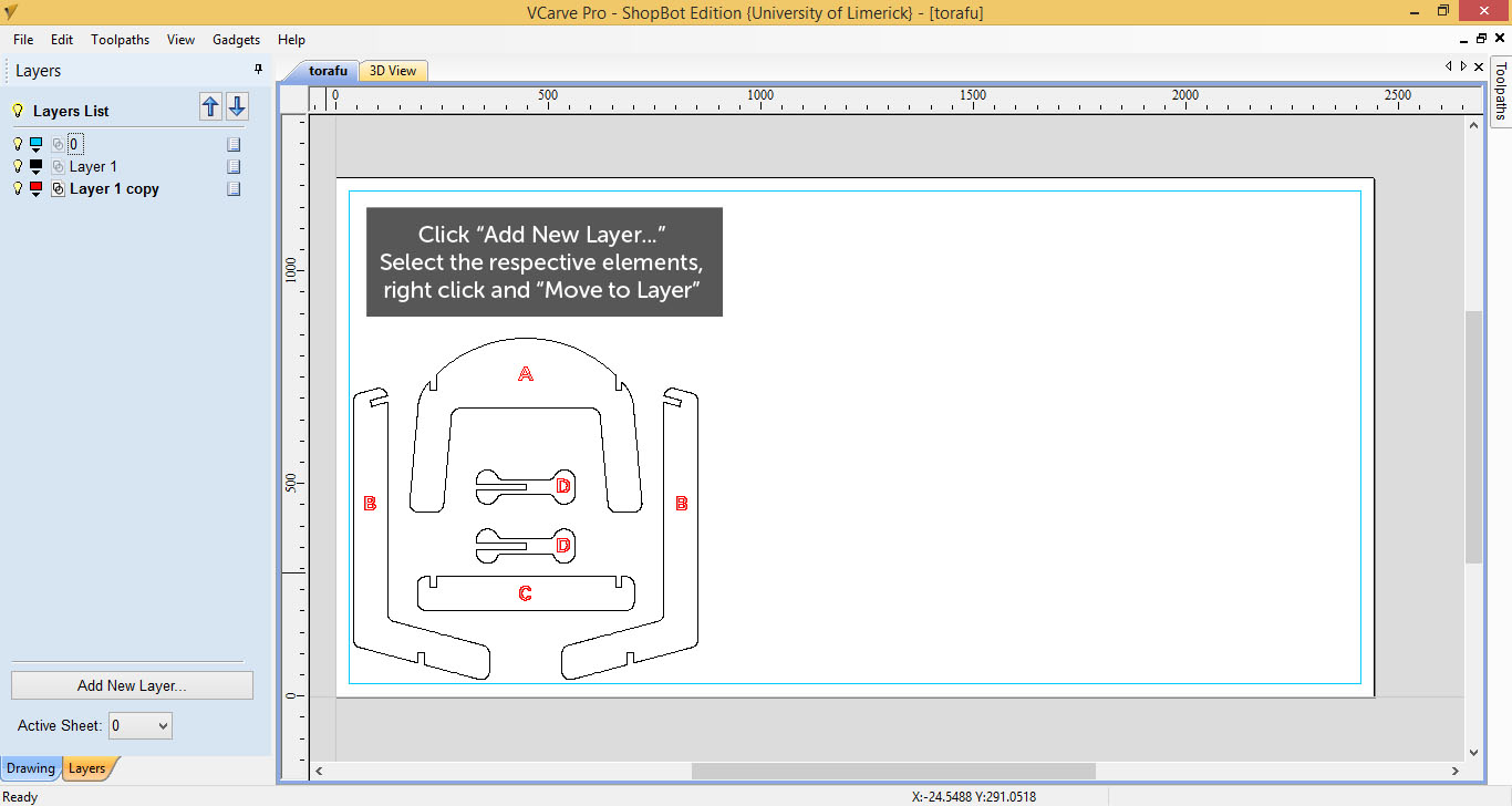
Name the layer and assign the layer a colour. Double-click the page symbol just left of the name text, to select all elements on the layer, so that you can easily assign toolpaths etc. This is very useful for lager, more complicated drawings.
5, Adding Fillets
Internal Corners - due to the thickness of the bits we are using - are given a normal fillet of the same diameter. This happens automatically when the software creates the offset for the toolpath, but it is not the only option.
The Fillet Tool in V-Carve Pro has 3 alternatives: The "Dog-Bone" Fillet, the "T-Bone" Fillet and the "Plasma/Drag Knife" Fillet The "Plasma/Drag Knife" Fillet is not for use with a router, but the first two are easily implemented solutions to avoid a lot of sanding or finishing to cut fitting parts on the CNC directly.
In the case of the Fillet Tool not working with the selected geometry, check the PolyLine with the Node Editor (It's the second mouse selection tool under Edit Objects). As you see below, there might be a lot of nodes or anchors describing a straight line, which keeps the fillet tool from being able to identify the corner properly. You can also use the Node Editor to remove the superfluous points, and allow the fillet to be added.
6, Adding a Profile Toolpath
Profile Toolpaths are cuts Outside, Inside or On a given line. To correctly assign an Outside or an Inside profile, a closed polyline is required. Open Polylines will not be calculated, and you will be given an error telling you how many were not selected.
- Select the outlines to be used (in pink dotted lines below)
- Click the
Profile Toolpathicon on the panel at the right. - Set the
Cut Depth (C). Usually a little more than the thickness of the material. In this case, 15.5mm for a 15mm sheet of Plywood. - Set the Tool to be used, with
Select .... A Compression bit is usually useful for profiles that go the whole way through the material.
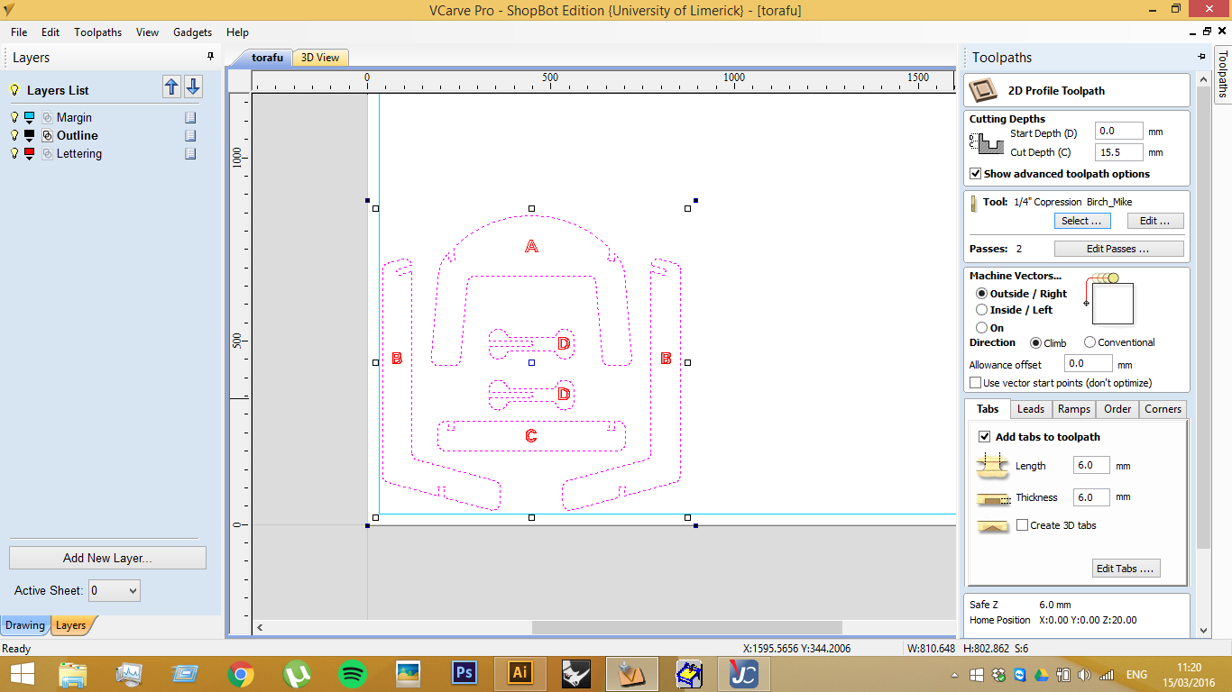
For parts that will be cut the whole way through, it is important to assign some tabs, which keep any of the cut parts from moving during the job, jamming against the machine or being expelled unexpectedly.
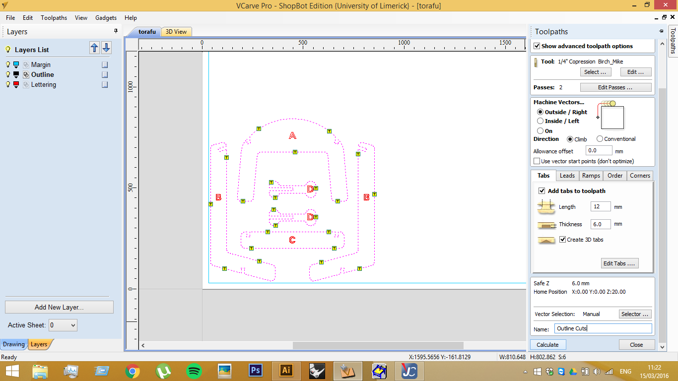
Click the Edit Tabs button, to bring up the Tabs screen. There are some options for automatic placement, but manual placement is better in most cases. Click to add a yellow marker. Click an existing marker to remove it, or drag it to a new position. Click Close when you are done. The sizes of the Tabs are set on the Toolpath screen.
With the tabs added, just click Calculate to finish. And then close the Profile panel.
7, Making a Pocket Toolpath
Pocket Toolpaths are set up similarly to Profile Toolpaths. Select the geometries first, and then the Pocket Icon on the right-hand panel.
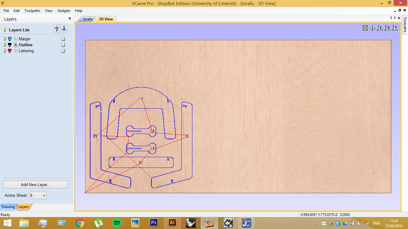
8, Generating Previews
In the Preview panel, you can see the following. Blue lines represent Cuts (centre of tool); Red lines represent Travel, (usually at a 6mm Safe Height above the material) and Green lines, which are vertical Plunge lines (not really visible here).
Note: this is actually a 3D preview - the controls are: LEFT MOUSE (click and drag) to Rotate; LEFT AND RIGHT MOUSE TOGETHER (click and drag) to Pan; and RIGHT MOUSE ONLY (click and drag) to Zoom.
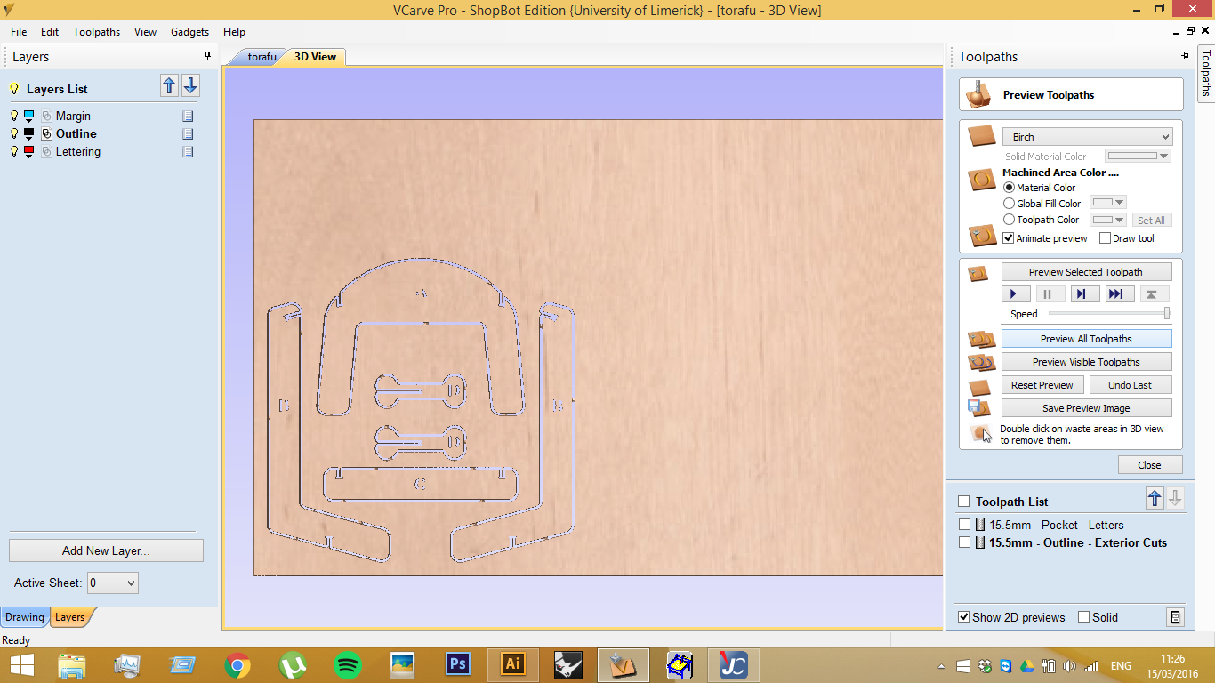
And if you click either Preview All Toolpaths or Preview Visible Toolpaths the resultant cuts are made on the material, with the settings applied from the tool library, job settings page and tab set-up.
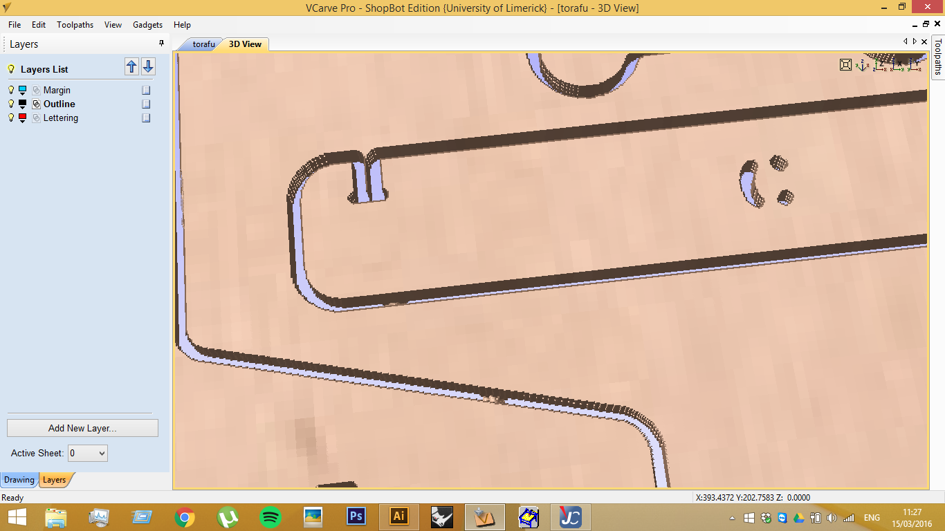
9, Making a change to a Toolpath
On closer inspection, you can see that this is not the result we were hoping for. The Tool used for the letters cannot fit into the narrower part of the type, and cut the whole way through.
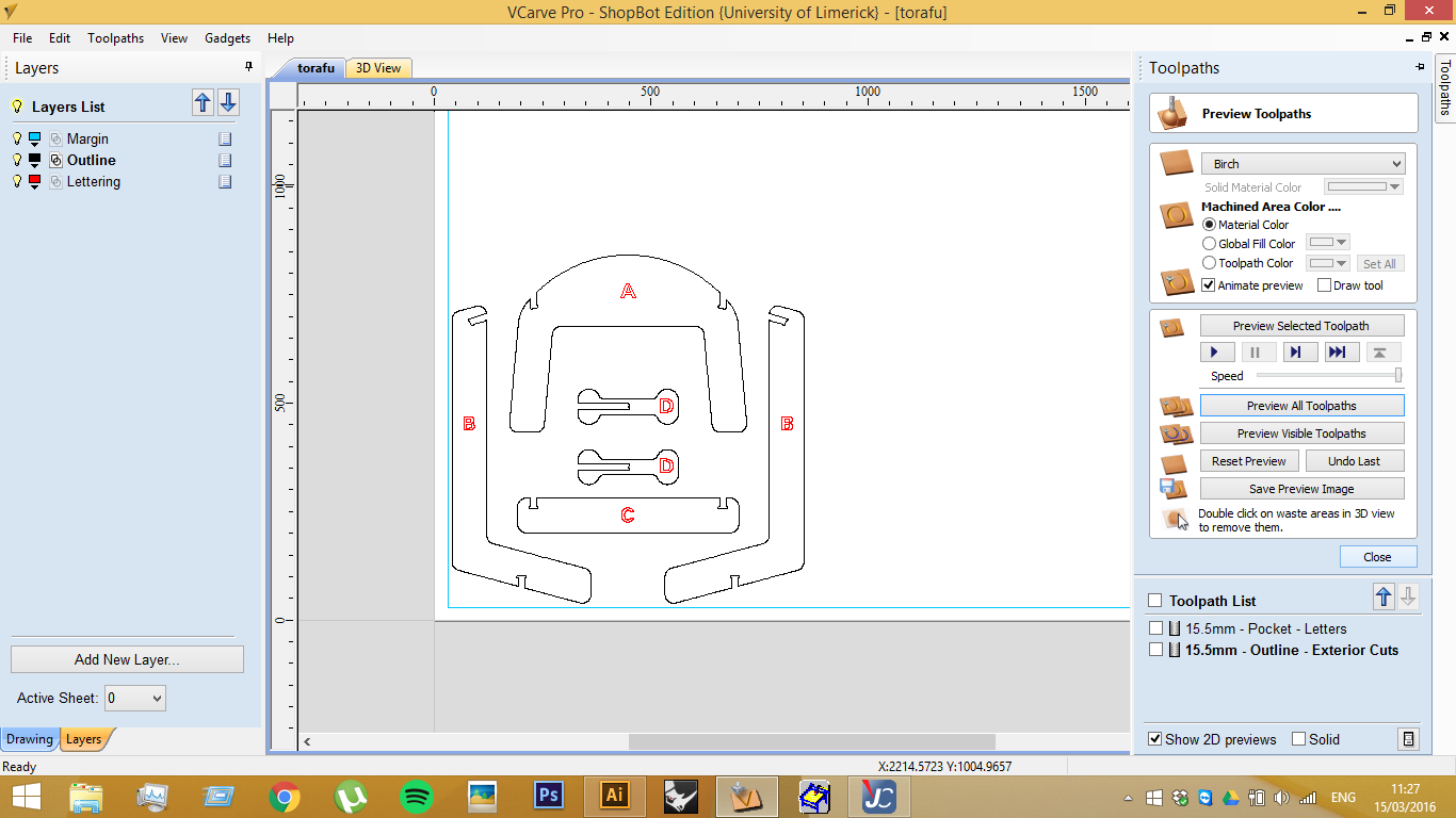
Return to the 2D view by clicking the tab immediately above the viewport. On the Toolpaths list at the right-hand-side double-click the name of the toolpath in question, ie. 15.5mm - Pocket - Letters.
Change for 1/8" (3.175mm) Downcut...
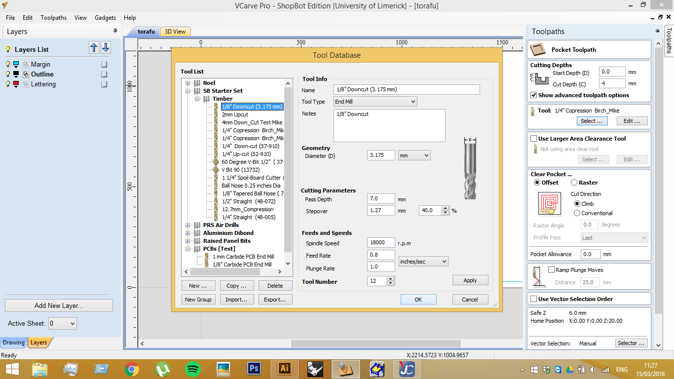
And Calculate again. It is possible to make other updates in exactly the same way. If you would like to modify the drawing - to move it, rotate it, add fillets or add/move tabs - just be sure to re-calculate it afterwards!
To recalculate everything at once, just right-click one of the ToolPaths on the list, and click Recalculate All on the menu.
10, Calculation etc.
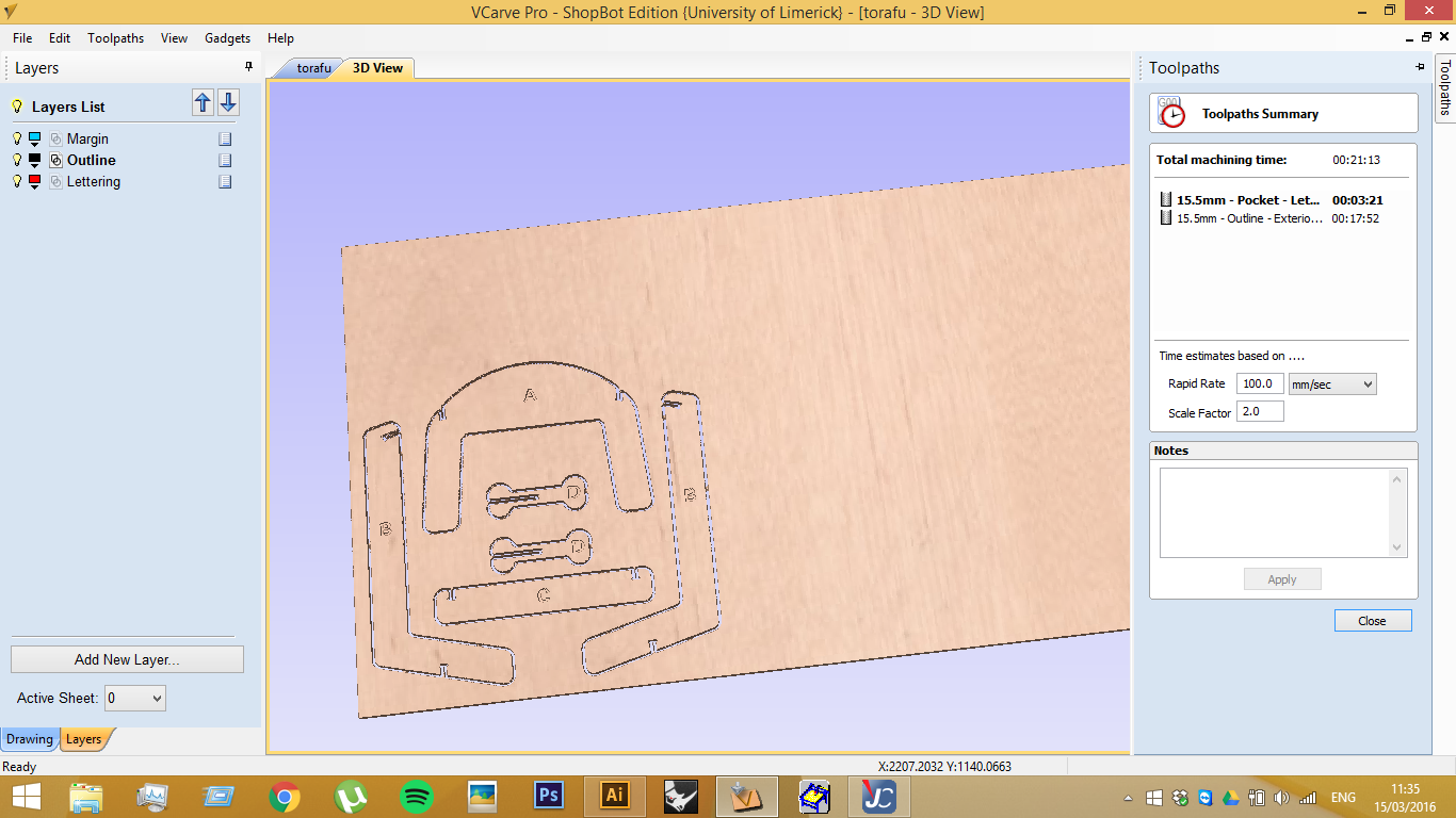
The symbol with the Time icon allows for calculations, which gives an estimate for how long a particular cut might take.
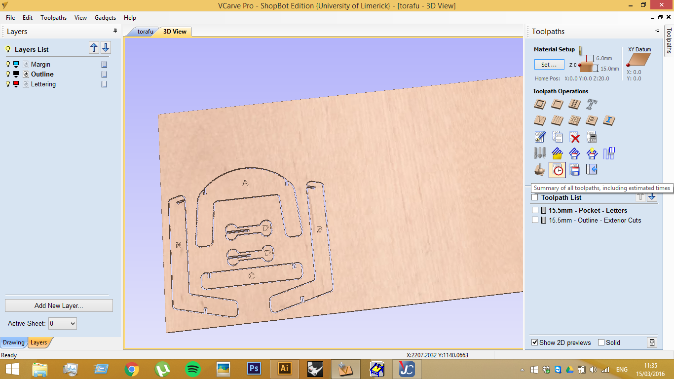
This shows the expected Total Machining Time and each individual Toolpath's time.
11, Exporting Toolpaths
Finally export your toolpaths with the Save Toolpaths button on the right-hand panel (as shown below).

For your confirmation, this panel shows the toolpaths to be saved, as well as the tool numbers, and description of the toolpaths. Everything you have checked in the list below will be exported.
If you have Output direct to Machine checked, you will see it say "Starting Controls". If you have not had a chance to do all of the calibrations and other preparations outlined on the Shopbot Step-by-step page, hit Cancel and prepare this now.
Uncheck Output direct to Machine to generate a static G-code or Part File. Part Files, once exported, are saved with a .SBP extension and can be run from the SB3 Controller on loading. The ShopBot controller program will automatically check the file header for ToolPath settings, feed rates, safe heights, etc.